How to Use Dual-Channel Digital Isolator: Examples, Pinouts, and Specs
Introduction
The ADuM1201 is a dual-channel digital isolator manufactured by Analog Devices Inc. It provides electrical isolation between two circuits while enabling the transmission of digital signals. This isolation is achieved using iCoupler® technology, which employs magnetic coupling to ensure robust performance and high-speed operation. The ADuM1201 is ideal for applications requiring protection from high voltages, noise immunity, and signal integrity across isolated domains.
Explore Projects Built with Dual-Channel Digital Isolator


Explore Projects Built with Dual-Channel Digital Isolator
Common Applications
- Microcontroller and sensor interface isolation
- Industrial automation and motor control
- Power supply and battery management systems
- Data communication in noisy environments
- Medical equipment requiring patient safety isolation
Technical Specifications
Key Specifications
| Parameter | Value |
|---|---|
| Isolation Voltage | 2.5 kV RMS |
| Data Rate | Up to 25 Mbps |
| Supply Voltage (VDD1/VDD2) | 2.7 V to 5.5 V |
| Propagation Delay | 45 ns (typical) |
| Common-Mode Transient Immunity (CMTI) | >25 kV/µs |
| Operating Temperature Range | -40°C to +125°C |
| Channels | 2 (1 forward, 1 reverse or 2 forward) |
| Package Options | 8-lead SOIC (narrow-body) |
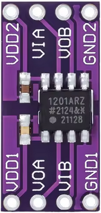
Pin Configuration and Descriptions
The ADuM1201 is available in an 8-lead SOIC package. The pinout and descriptions are as follows:
| Pin Number | Pin Name | Description |
|---|---|---|
| 1 | VDD1 | Supply voltage for side 1 (2.7 V to 5.5 V) |
| 2 | GND1 | Ground for side 1 |
| 3 | IN1 | Digital input for channel 1 |
| 4 | IN2 | Digital input for channel 2 |
| 5 | OUT2 | Digital output for channel 2 |
| 6 | OUT1 | Digital output for channel 1 |
| 7 | GND2 | Ground for side 2 |
| 8 | VDD2 | Supply voltage for side 2 (2.7 V to 5.5 V) |
Usage Instructions
How to Use the ADuM1201 in a Circuit
- Power Supply: Connect VDD1 and VDD2 to separate power supplies (2.7 V to 5.5 V). Ensure that GND1 and GND2 are isolated from each other to maintain proper isolation.
- Signal Connections:
- Connect the digital input signals to IN1 and IN2.
- The corresponding isolated outputs will appear on OUT1 and OUT2.
- Bypass Capacitors: Place decoupling capacitors (e.g., 0.1 µF) close to VDD1 and VDD2 pins to reduce noise and ensure stable operation.
- PCB Layout: Maintain sufficient spacing between the isolated sides to prevent breakdown and ensure compliance with isolation standards.
Important Considerations
- Isolation Voltage: Do not exceed the rated isolation voltage of 2.5 kV RMS.
- Data Rate: Ensure the input signal frequency does not exceed the maximum data rate of 25 Mbps.
- Thermal Management: Operate within the specified temperature range (-40°C to +125°C) to avoid thermal stress.
- Signal Integrity: Use short and direct traces for input and output signals to minimize noise and signal degradation.
Example: Connecting to an Arduino UNO
The ADuM1201 can be used to isolate an Arduino UNO from a high-voltage circuit. Below is an example of how to connect and program the ADuM1201 for isolating a digital signal.
Circuit Diagram
- Connect VDD1 and GND1 to the Arduino's 5V and GND pins, respectively.
- Connect VDD2 and GND2 to the isolated circuit's power supply.
- Connect a digital output pin (e.g., D2) of the Arduino to IN1.
- OUT1 will provide the isolated signal to the high-voltage circuit.
Arduino Code
// Example code to toggle a digital signal through the ADuM1201
const int signalPin = 2; // Arduino pin connected to IN1 of ADuM1201

void setup() {
  pinMode(signalPin, OUTPUT); // Set signalPin as an output
}

void loop() {
  digitalWrite(signalPin, HIGH); // Send a HIGH signal
  delay(1000); // Wait for 1 second
  digitalWrite(signalPin, LOW);  // Send a LOW signal
  delay(1000); // Wait for 1 second
}
Troubleshooting and FAQs
Common Issues and Solutions
No Signal on Output Pins
- Cause: Missing or incorrect power supply connections.
- Solution: Verify that VDD1 and VDD2 are powered correctly and that GND1 and GND2 are isolated.
Signal Distortion or Noise
- Cause: Insufficient decoupling or long signal traces.
- Solution: Add bypass capacitors near the VDD pins and minimize trace lengths.
Exceeding Isolation Voltage
- Cause: High voltage spikes or improper grounding.
- Solution: Ensure the voltage across the isolation barrier does not exceed 2.5 kV RMS.
Overheating
- Cause: Operating outside the specified temperature range or excessive current draw.
- Solution: Check the operating conditions and ensure proper thermal management.
FAQs
Q1: Can the ADuM1201 handle bidirectional communication?
A1: No, the ADuM1201 is designed for unidirectional communication. For bidirectional communication, consider using other isolators with dedicated bidirectional channels.
Q2: What is the maximum distance between the isolated sides?
A2: The maximum distance is determined by the PCB layout and isolation standards. Ensure sufficient spacing to maintain the rated isolation voltage.
Q3: Can I use the ADuM1201 for analog signals?
A3: No, the ADuM1201 is designed for digital signals only. For isolating analog signals, consider using analog isolators.
Q4: Is the ADuM1201 suitable for medical applications?
A4: Yes, the ADuM1201 can be used in medical applications, provided it meets the required isolation and safety standards for the specific use case.