How to Use Linear Actuator: Examples, Pinouts, and Specs
Introduction
A linear actuator is a device that creates motion in a straight line, typically used to convert rotational motion into linear motion. Manufactured by TI Motions, this component is widely used in automation, robotics, and industrial applications to control the position of objects. Linear actuators are essential in systems requiring precise linear movement, such as adjustable furniture, conveyor belts, and robotic arms.
Explore Projects Built with Linear Actuator
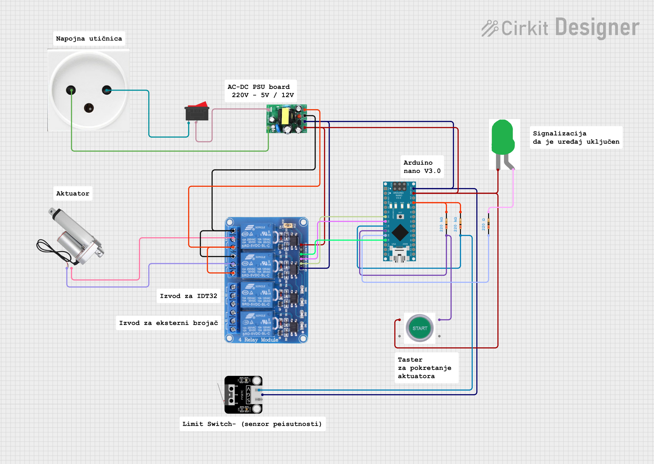
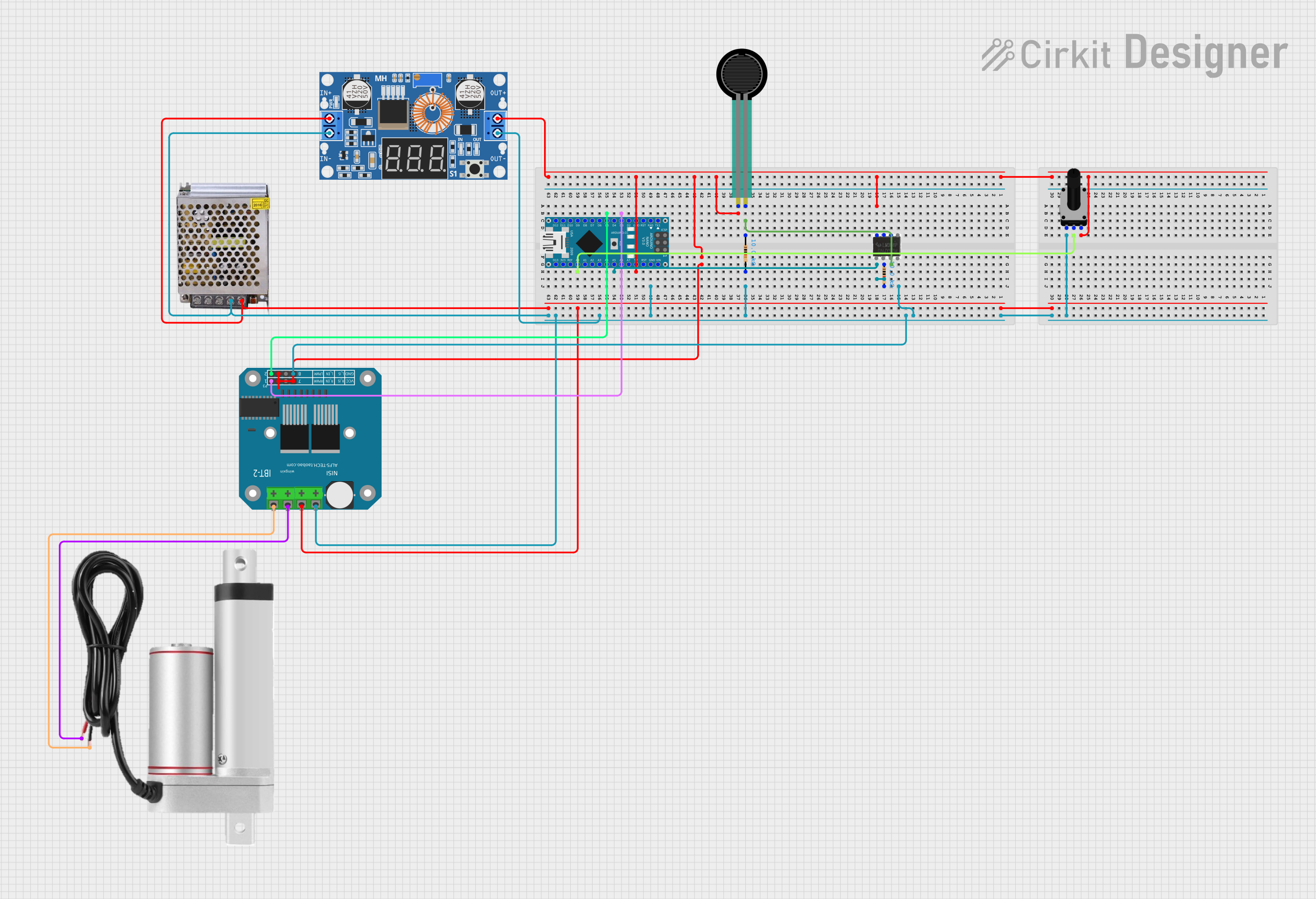
Explore Projects Built with Linear Actuator
Common Applications
- Automation Systems: Used in factory automation for precise positioning.
- Robotics: Enables robotic arms to perform linear movements.
- Medical Equipment: Found in hospital beds and patient lifts.
- Adjustable Furniture: Used in height-adjustable desks and reclining chairs.
- Solar Trackers: Adjusts the angle of solar panels for optimal sunlight exposure.
Technical Specifications
Below are the key technical details for the TI Motions linear actuator:
| Parameter | Specification |
|---|---|
| Input Voltage | 12V DC / 24V DC |
| Maximum Load Capacity | 6000 N (Newtons) |
| Stroke Length | 50 mm to 1000 mm (customizable) |
| Speed | 4 mm/s to 50 mm/s (varies with load) |
| Duty Cycle | 10% (2 minutes on, 18 minutes off) |
| Operating Temperature | -20°C to +65°C |
| Protection Class | IP54 (standard), IP66 (optional) |
| Feedback Options | Potentiometer, Hall Sensor, or None |
Pin Configuration and Descriptions
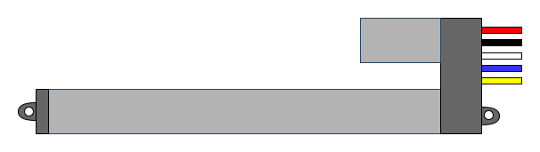
The linear actuator typically comes with a 4-wire configuration for models with feedback. Below is the pinout description:
| Pin | Wire Color | Function |
|---|---|---|
| 1 | Red | Positive Power Supply (V+) |
| 2 | Black | Negative Power Supply (GND) |
| 3 | White | Feedback Signal (e.g., Potentiometer) |
| 4 | Yellow | Feedback Signal (e.g., Hall Sensor) |
For models without feedback, only the red and black wires are used for power.
Usage Instructions
How to Use the Linear Actuator in a Circuit
- Power Supply: Connect the red wire to the positive terminal of a 12V or 24V DC power supply, depending on the actuator's rating. Connect the black wire to the ground terminal.
- Control: Use a DPDT (Double Pole Double Throw) switch or an H-bridge motor driver to control the direction of movement (extend/retract).
- Feedback (Optional): If the actuator includes feedback, connect the white and yellow wires to an analog input or microcontroller pins to monitor position.
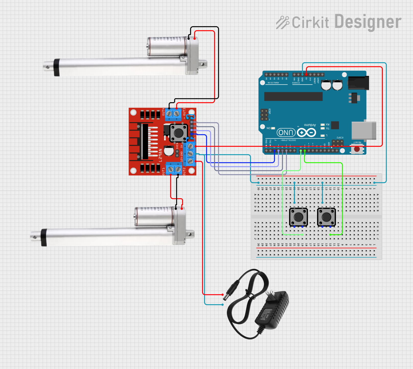
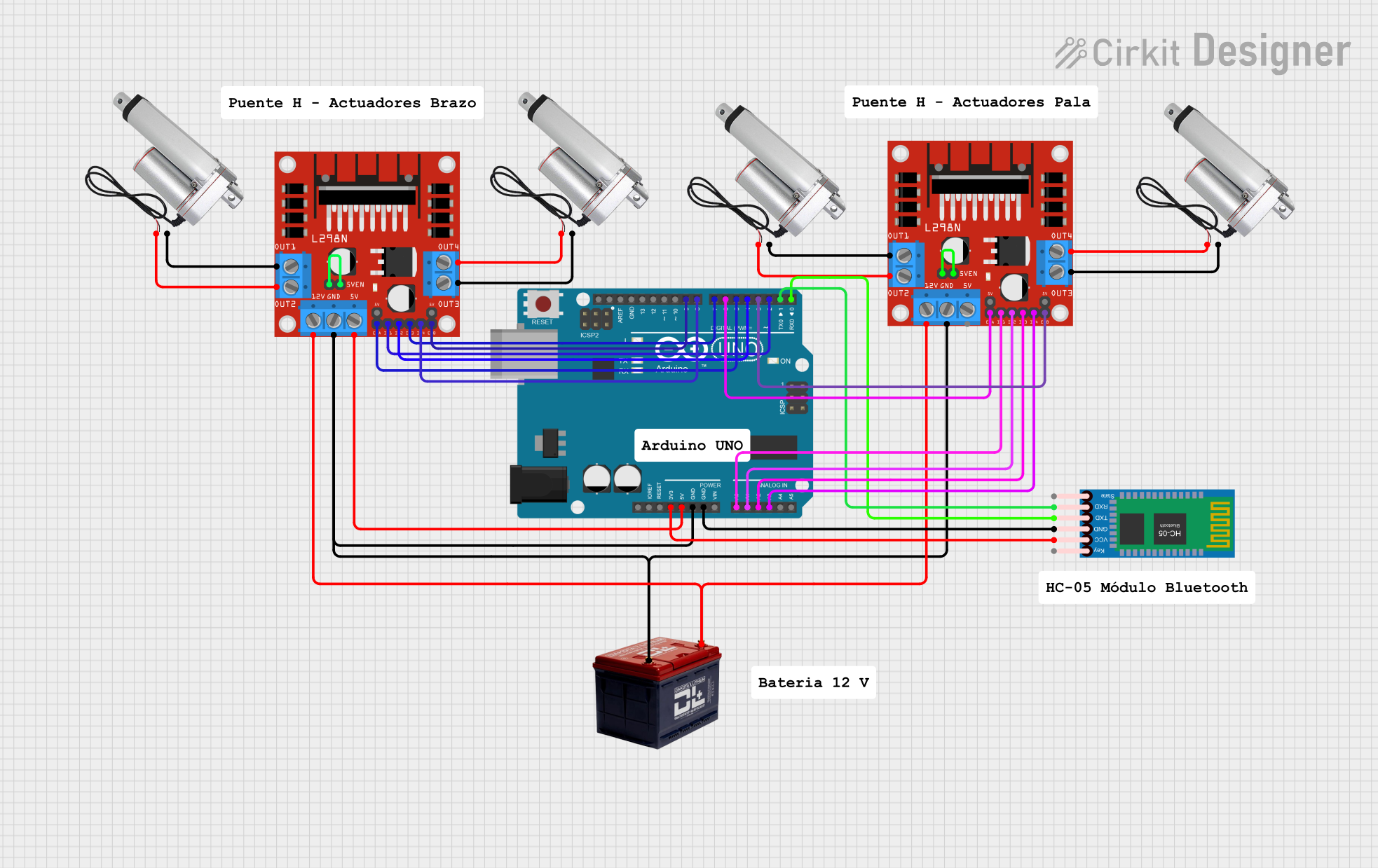
Example Circuit with Arduino UNO
Below is an example of how to control a linear actuator with an Arduino UNO and an L298N motor driver:
Circuit Connections
- L298N Motor Driver:
- Connect the actuator's red and black wires to the motor output terminals (OUT1 and OUT2).
- Connect the motor driver's input pins (IN1 and IN2) to Arduino digital pins 8 and 9.
- Connect the motor driver's 12V power input to an external power supply.
- Arduino:
- Connect the motor driver's GND to the Arduino GND.
- If feedback is available, connect the white wire to an analog input pin (e.g., A0).
Arduino Code
// Define motor control pins
const int motorPin1 = 8; // IN1 on L298N
const int motorPin2 = 9; // IN2 on L298N
const int feedbackPin = A0; // Feedback signal (optional)

void setup() {
  // Set motor pins as outputs
  pinMode(motorPin1, OUTPUT);
  pinMode(motorPin2, OUTPUT);

  // Set feedback pin as input
  pinMode(feedbackPin, INPUT);

  Serial.begin(9600); // Initialize serial communication
}

void loop() {
  // Extend the actuator
  digitalWrite(motorPin1, HIGH);
  digitalWrite(motorPin2, LOW);
  delay(2000); // Run for 2 seconds

  // Stop the actuator
  digitalWrite(motorPin1, LOW);
  digitalWrite(motorPin2, LOW);
  delay(1000); // Pause for 1 second

  // Retract the actuator
  digitalWrite(motorPin1, LOW);
  digitalWrite(motorPin2, HIGH);
  delay(2000); // Run for 2 seconds

  // Stop the actuator
  digitalWrite(motorPin1, LOW);
  digitalWrite(motorPin2, LOW);
  delay(1000); // Pause for 1 second

  // Read feedback (if available)
  int feedbackValue = analogRead(feedbackPin);
  Serial.print("Feedback Value: ");
  Serial.println(feedbackValue);
}
Important Considerations
- Power Supply: Ensure the power supply matches the actuator's voltage rating (12V or 24V).
- Duty Cycle: Do not exceed the specified duty cycle (e.g., 10%) to prevent overheating.
- Load Capacity: Avoid exceeding the maximum load capacity to ensure reliable operation.
- Feedback: If using feedback, calibrate the actuator's position based on the feedback signal.
Troubleshooting and FAQs
Common Issues and Solutions
Actuator Does Not Move:
- Check the power supply voltage and connections.
- Verify that the control signals (e.g., from the Arduino or switch) are correct.
- Ensure the load does not exceed the actuator's capacity.
Actuator Moves in One Direction Only:
- Inspect the motor driver or switch wiring for errors.
- Confirm that both control signals (IN1 and IN2) are functioning.
Overheating:
- Ensure the actuator is not operating beyond its duty cycle.
- Reduce the load or operating time if necessary.
Inaccurate Feedback:
- Verify the feedback wiring and connections.
- Calibrate the feedback signal in your control system.
FAQs
Q: Can I use the actuator outdoors?
A: Yes, but ensure the actuator has an appropriate IP rating (e.g., IP66) for protection against dust and water.
Q: How do I determine the stroke length I need?
A: Measure the required linear movement range and select an actuator with a stroke length slightly longer than your requirement.
Q: Can I control the speed of the actuator?
A: Yes, by using a PWM (Pulse Width Modulation) signal with a motor driver, you can adjust the speed.
Q: What happens if I exceed the duty cycle?
A: Exceeding the duty cycle can cause the actuator to overheat, potentially damaging the motor or reducing its lifespan. Always adhere to the specified duty cycle.
This documentation provides a comprehensive guide to using the TI Motions linear actuator effectively. For further assistance, consult the manufacturer's datasheet or technical support.