Cirkit Designer
Your all-in-one circuit design IDE
Home /
Component Documentation
How to Use INA228: Examples, Pinouts, and Specs
Introduction
The INA228 is a high-precision, low-power current shunt monitor designed to measure small voltage drops across a shunt resistor. It features a wide common-mode voltage range (up to 85V) and provides a digital output proportional to the current flowing through the shunt. This makes it an excellent choice for applications requiring accurate current, voltage, and power monitoring.
Explore Projects Built with INA228
Battery-Powered Load Cell Amplifier with INA125 and LM324

This circuit is a load cell signal conditioning and amplification system. It uses an INA125 instrumentation amplifier to amplify the differential signal from a load cell, with additional filtering and gain control provided by potentiometers and capacitors. The amplified signal is then monitored by a digital voltmeter, and the entire system is powered by a 12V battery with a step-up boost converter to provide stable voltage.
Solar-Powered Battery Management System with Wi-Fi Connectivity and Environmental Sensing
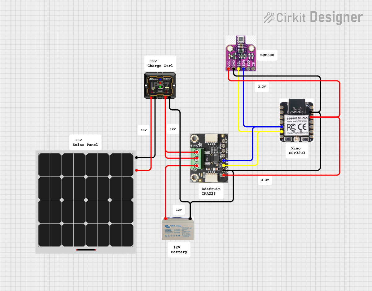
This circuit is designed for solar power management and monitoring. It includes a solar panel connected to an MPPT 12V charge controller, which in turn charges a 12V AGM battery. The Adafruit INA228 current and voltage sensor is used to monitor the power flow from the solar panel to the battery, and the Xiao esp32c3 microcontroller, along with a BME680 environmental sensor, are interfaced via I2C for data processing and environmental monitoring.
ESP32 and INA3221-Based Smart Power Monitoring System with Bluetooth and Environmental Sensing
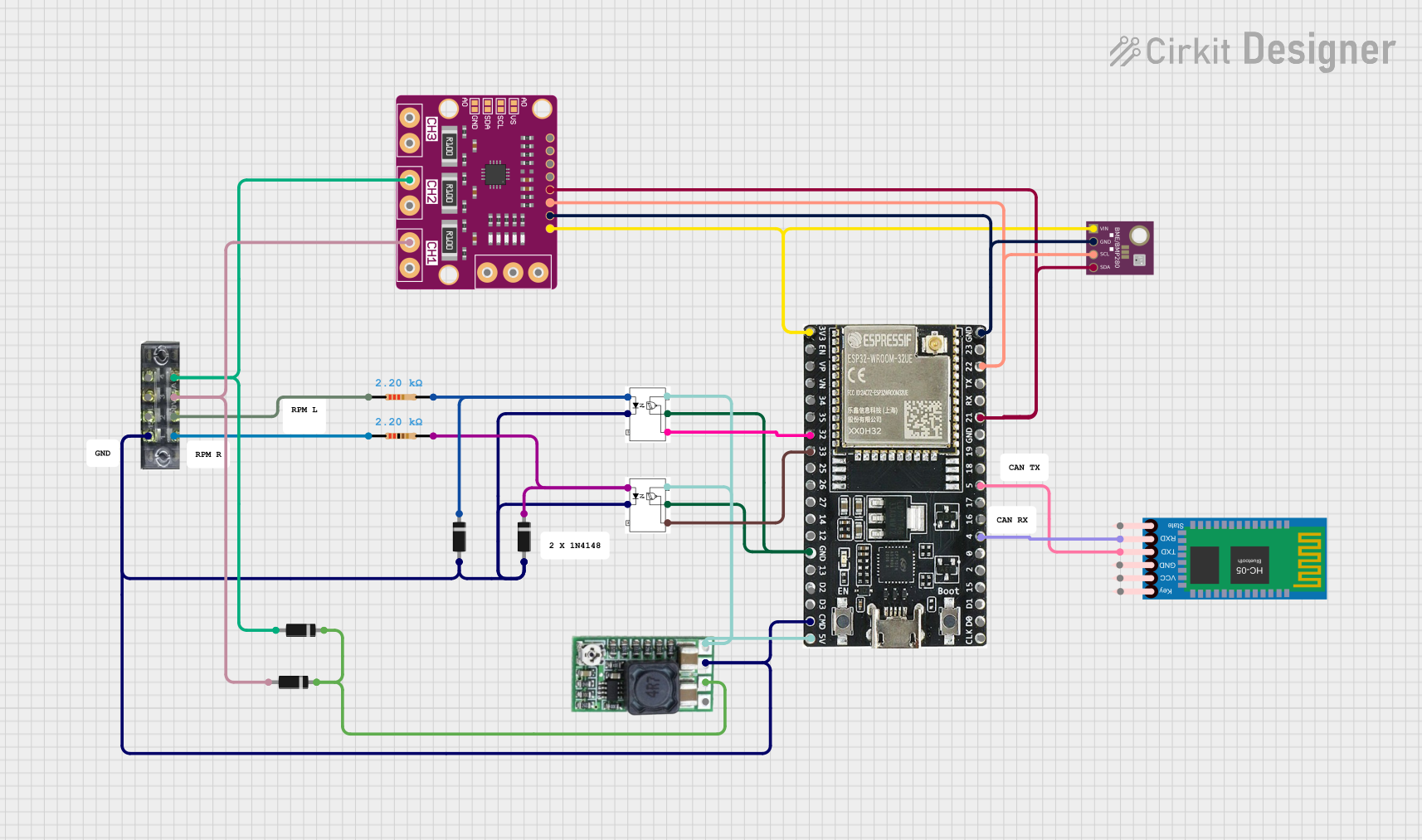
This circuit is a sensor monitoring and communication system that uses an ESP32 microcontroller to read data from a BME/BMP280 environmental sensor and an INA3221 power monitor. The ESP32 communicates with the sensors via I2C and transmits data wirelessly using an HC-05 Bluetooth module. Additionally, the circuit includes optocouplers and diodes for signal isolation and protection.
Nucleo 401RE Controlled Robotic Motor with Vibration Feedback and ADXL345 Accelerometer
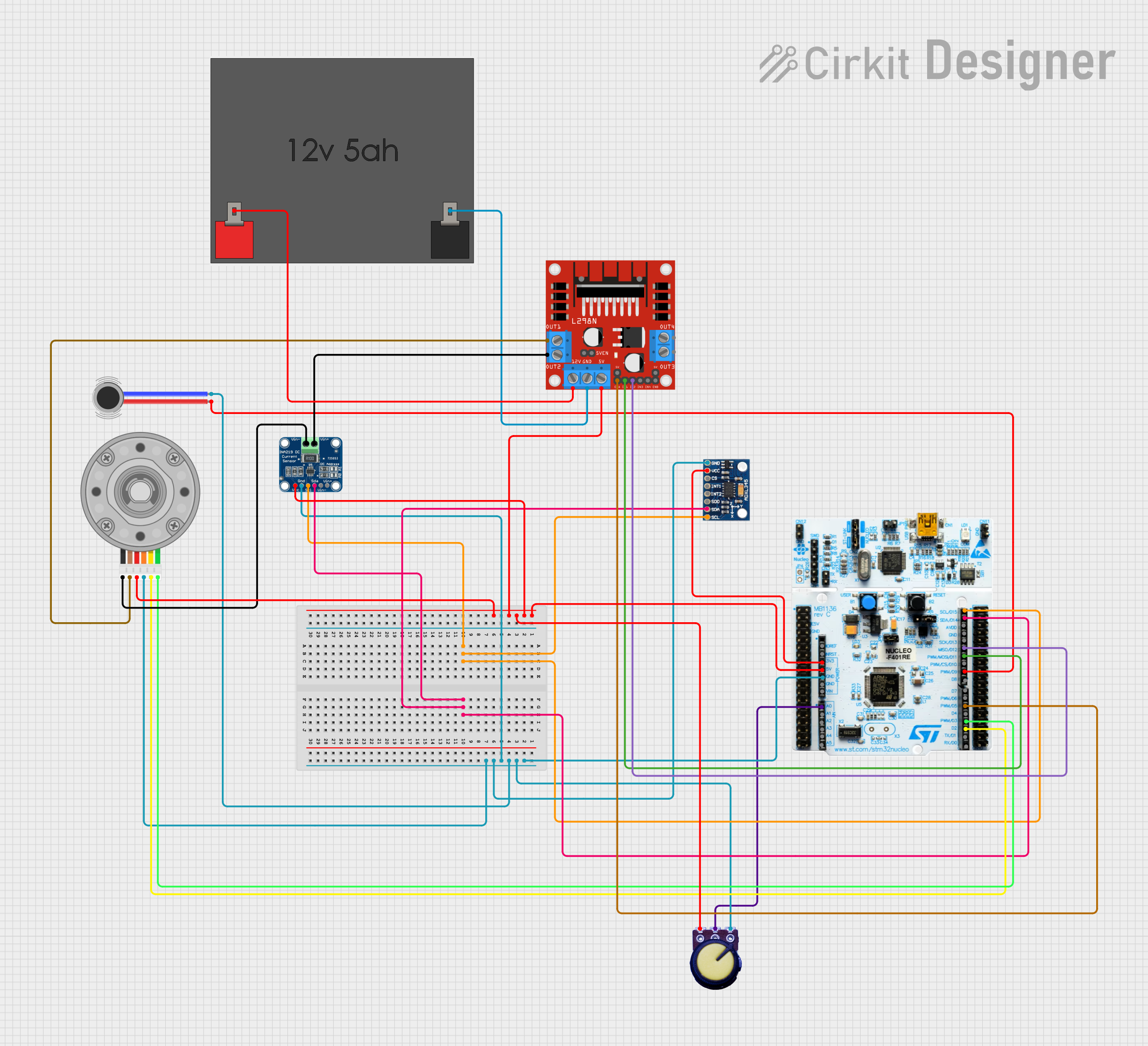
This circuit features a Nucleo 401RE microcontroller as the central processing unit, interfacing with an ADXL345 accelerometer and an INA219 current sensor over an I2C bus for motion sensing and power monitoring, respectively. A DC motor with an encoder is driven by an L298N motor driver, with speed control potentially provided by a connected potentiometer and vibration feedback through a vibration motor. The system is powered by a 12V battery, with voltage regulation provided for the various components.
Explore Projects Built with INA228
Battery-Powered Load Cell Amplifier with INA125 and LM324
This circuit is a load cell signal conditioning and amplification system. It uses an INA125 instrumentation amplifier to amplify the differential signal from a load cell, with additional filtering and gain control provided by potentiometers and capacitors. The amplified signal is then monitored by a digital voltmeter, and the entire system is powered by a 12V battery with a step-up boost converter to provide stable voltage.
Solar-Powered Battery Management System with Wi-Fi Connectivity and Environmental Sensing
This circuit is designed for solar power management and monitoring. It includes a solar panel connected to an MPPT 12V charge controller, which in turn charges a 12V AGM battery. The Adafruit INA228 current and voltage sensor is used to monitor the power flow from the solar panel to the battery, and the Xiao esp32c3 microcontroller, along with a BME680 environmental sensor, are interfaced via I2C for data processing and environmental monitoring.
ESP32 and INA3221-Based Smart Power Monitoring System with Bluetooth and Environmental Sensing
This circuit is a sensor monitoring and communication system that uses an ESP32 microcontroller to read data from a BME/BMP280 environmental sensor and an INA3221 power monitor. The ESP32 communicates with the sensors via I2C and transmits data wirelessly using an HC-05 Bluetooth module. Additionally, the circuit includes optocouplers and diodes for signal isolation and protection.
Nucleo 401RE Controlled Robotic Motor with Vibration Feedback and ADXL345 Accelerometer
This circuit features a Nucleo 401RE microcontroller as the central processing unit, interfacing with an ADXL345 accelerometer and an INA219 current sensor over an I2C bus for motion sensing and power monitoring, respectively. A DC motor with an encoder is driven by an L298N motor driver, with speed control potentially provided by a connected potentiometer and vibration feedback through a vibration motor. The system is powered by a 12V battery, with voltage regulation provided for the various components.
Common Applications
- Battery management systems
- Power monitoring in servers and data centers
- Solar inverters and energy storage systems
- Industrial automation and motor control
- Electric vehicle (EV) power systems
Technical Specifications
Key Technical Details
| Parameter | Value |
|---|---|
| Supply Voltage (VCC) | 2.7V to 5.5V |
| Common-Mode Voltage Range | -0.3V to +85V |
| Input Offset Voltage | ±10 µV (typical) |
| Current Measurement Range | Configurable via external shunt resistor |
| Communication Interface | I²C or SMBus |
| Resolution | 20-bit |
| Operating Temperature Range | -40°C to +125°C |
| Power Consumption | 300 µA (typical) |
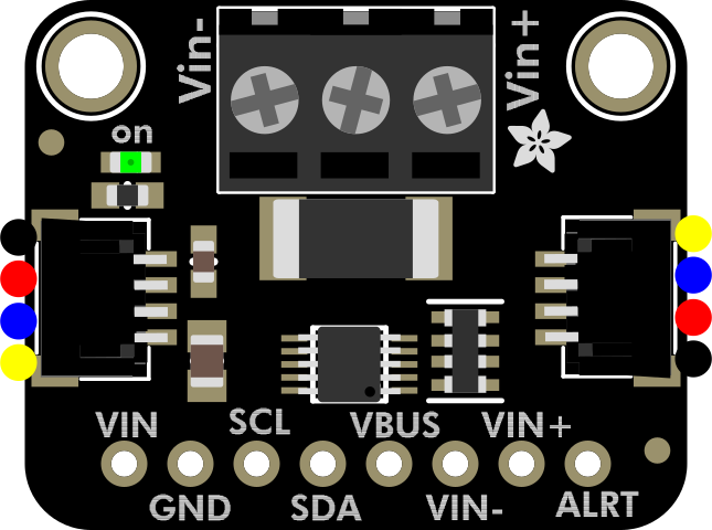
Pin Configuration and Descriptions
The INA228 is typically available in a 10-pin WSON package. Below is the pinout and description:
| Pin Number | Pin Name | Description |
|---|---|---|
| 1 | VIN+ | Positive input for shunt voltage measurement |
| 2 | VIN- | Negative input for shunt voltage measurement |
| 3 | GND | Ground connection |
| 4 | SCL | I²C clock line |
| 5 | SDA | I²C data line |
| 6 | ALERT | Alert output for over-limit conditions |
| 7 | VCC | Power supply input (2.7V to 5.5V) |
| 8 | ADDR | Address selection for I²C communication |
| 9 | NC | No connection (leave floating) |
| 10 | NC | No connection (leave floating) |
Usage Instructions
How to Use the INA228 in a Circuit
- Power Supply: Connect the VCC pin to a 2.7V to 5.5V power source and the GND pin to ground.
- Shunt Resistor: Place a precision shunt resistor between the VIN+ and VIN- pins. The resistor value should be chosen based on the expected current range.
- I²C Communication: Connect the SCL and SDA pins to the corresponding I²C lines of your microcontroller. Use pull-up resistors (typically 4.7kΩ) on these lines.
- Address Configuration: Set the I²C address using the ADDR pin. Refer to the datasheet for address selection details.
- Alert Pin: Optionally, connect the ALERT pin to a microcontroller GPIO for over-limit condition monitoring.
Important Considerations
- Use a low-inductance, high-precision shunt resistor to ensure accurate measurements.
- Ensure the common-mode voltage does not exceed the specified range (-0.3V to +85V).
- Keep the traces between the shunt resistor and the INA228 as short as possible to minimize noise.
- Use decoupling capacitors (e.g., 0.1µF) near the VCC pin to stabilize the power supply.
Example Code for Arduino UNO
Below is an example of how to interface the INA228 with an Arduino UNO using the I²C protocol:
#include <Wire.h>

// INA228 I2C address (default is 0x40, but check your configuration)
#define INA228_ADDRESS 0x40

void setup() {
  Wire.begin(); // Initialize I2C communication
  Serial.begin(9600); // Initialize serial communication for debugging

  // Configure INA228 (example: set calibration register)
  Wire.beginTransmission(INA228_ADDRESS);
  Wire.write(0x05); // Calibration register address
  Wire.write(0x00); // High byte of calibration value
  Wire.write(0x10); // Low byte of calibration value
  Wire.endTransmission();

  Serial.println("INA228 initialized.");
}

void loop() {
  // Request shunt voltage measurement
  Wire.beginTransmission(INA228_ADDRESS);
  Wire.write(0x01); // Shunt voltage register address
  Wire.endTransmission();

  Wire.requestFrom(INA228_ADDRESS, 2); // Request 2 bytes of data
  if (Wire.available() == 2) {
    int16_t shuntVoltage = (Wire.read() << 8) | Wire.read();
    float voltage = shuntVoltage * 0.00000125; // Convert to volts (example scaling)
    Serial.print("Shunt Voltage: ");
    Serial.print(voltage, 6);
    Serial.println(" V");
  }

  delay(1000); // Wait 1 second before the next reading
}
Notes on the Code
- Replace the calibration value and scaling factor with values specific to your application.
- Ensure the I²C address matches the configuration of your INA228.
Troubleshooting and FAQs
Common Issues
No I²C Communication:
- Ensure the SCL and SDA lines are connected properly.
- Verify the pull-up resistors on the I²C lines.
- Check the I²C address configuration.
Incorrect Measurements:
- Verify the shunt resistor value and connections.
- Ensure the common-mode voltage is within the specified range.
- Check for noise or interference on the shunt resistor traces.
Alert Pin Not Functioning:
- Confirm the alert threshold configuration in the INA228 registers.
- Ensure the ALERT pin is connected to a valid GPIO.
Tips for Troubleshooting
- Use an oscilloscope or logic analyzer to monitor the I²C communication.
- Double-check all connections and component values.
- Refer to the INA228 datasheet for detailed register descriptions and configuration options.