Cirkit Designer Logo
Cirkit Designer
Your all-in-one circuit design IDE
Home / 
Component Documentation

How to Use Adafruit ICM20948: Examples, Pinouts, and Specs

Image of Adafruit ICM20948
Cirkit Designer LogoDesign with Adafruit ICM20948 in Cirkit Designer

Introduction

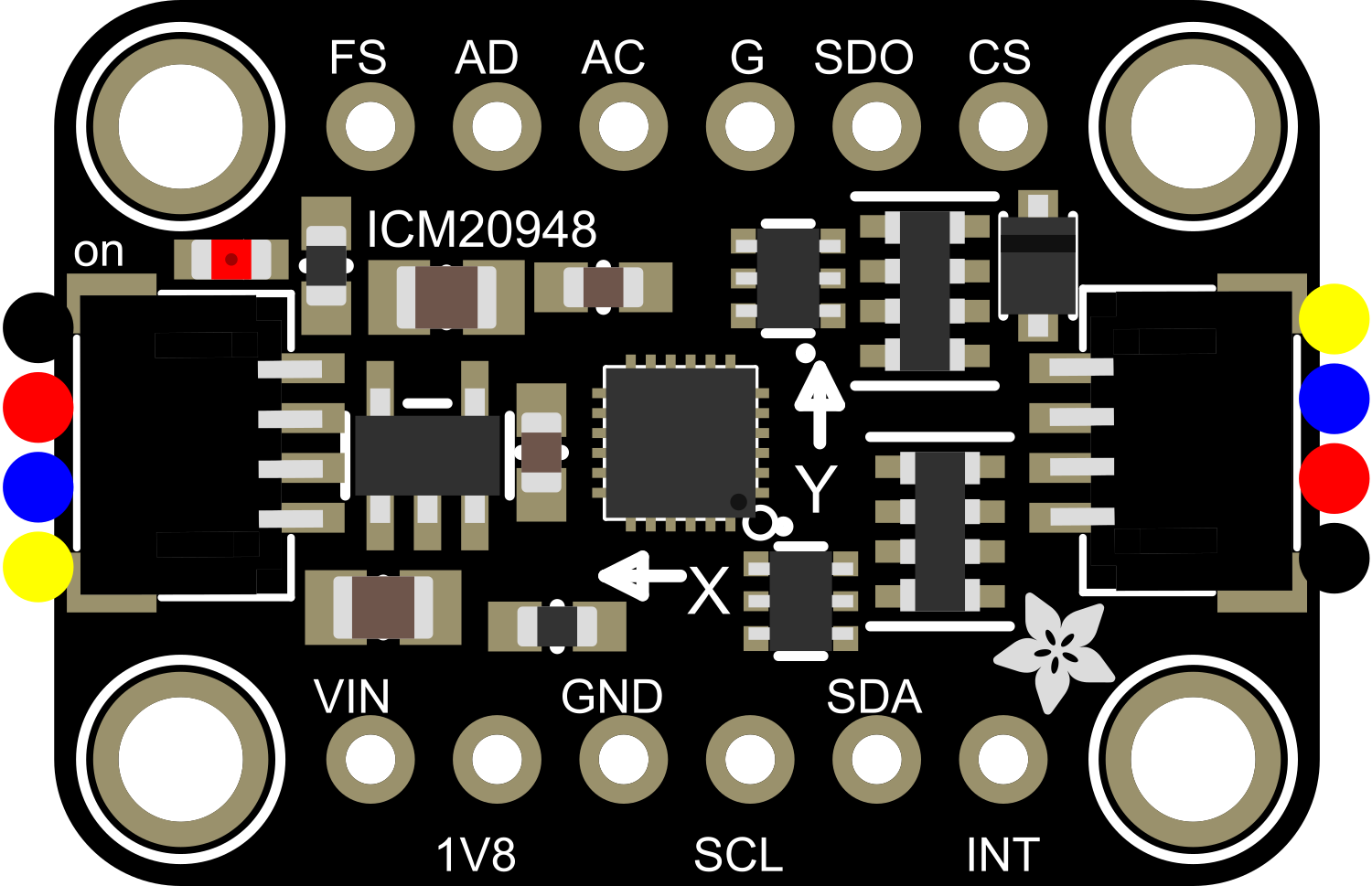
The Adafruit ICM20948 is a sophisticated 9-axis motion tracking module that integrates a 3-axis accelerometer, a 3-axis gyroscope, and a 3-axis magnetometer. This compact sensor is ideal for applications in robotics, virtual reality systems, drones, and motion tracking devices. It provides precise measurements for orientation, acceleration, and magnetic fields, making it a versatile component for a wide range of projects.

Explore Projects Built with Adafruit ICM20948

Use Cirkit Designer to design, explore, and prototype these projects online. Some projects support real-time simulation. Click "Open Project" to start designing instantly!
ESP32-Based Motion Tracking System with ICM20948 Sensor
Image of ICM20948: A project utilizing Adafruit ICM20948 in a practical application
This circuit features a SparkFun ESP32 Thing Plus microcontroller interfaced with an Adafruit ICM20948 9-axis motion sensor via an Adafruit TXB0104 4-channel bi-directional level shifter. The ESP32 reads data from the ICM20948 sensor, calculates orientation angles such as pitch, roll, yaw, and azimuth, and outputs these values to the serial monitor. The level shifter ensures compatibility between the 3.3V logic levels of the ESP32 and the 1.8V logic levels required by the ICM20948.
Cirkit Designer LogoOpen Project in Cirkit Designer
Raspberry Pi 4B-Based Multi-Sensor Interface Hub with GPS and GSM
Image of Rocket: A project utilizing Adafruit ICM20948 in a practical application
This circuit features a Raspberry Pi 4B interfaced with an IMX296 color global shutter camera, a Neo 6M GPS module, an Adafruit BMP388 barometric pressure sensor, an MPU-6050 accelerometer/gyroscope, and a Sim800l GSM module for cellular connectivity. Power management is handled by an MT3608 boost converter, which steps up the voltage from a Lipo battery, with a resettable fuse PTC and a 1N4007 diode for protection. The Adafruit Perma-Proto HAT is used for organizing connections and interfacing the sensors and modules with the Raspberry Pi via I2C and GPIO pins.
Cirkit Designer LogoOpen Project in Cirkit Designer
Arduino Mega 2560-Controlled Stepper Motors with RFID Access and Traffic Light Indication
Image of Copy of test: A project utilizing Adafruit ICM20948 in a practical application
This circuit controls two 28BYJ-48 stepper motors using A4988 stepper motor driver carriers, interfaced with an Arduino Mega 2560 microcontroller. It features an RFID-RC522 module for RFID reading, a 16x4 LCD display with I2C interface for user interaction, and a piezo speaker for audio feedback. Additionally, there is a traffic light module controlled by the Arduino, and a 48V to 5V converter to step down voltage for the logic levels. The power supply provides 12V to the motor drivers and is connected to a standard power outlet.
Cirkit Designer LogoOpen Project in Cirkit Designer
Battery-Powered Sensor Hub with Adafruit QT Py RP2040 and OLED Display
Image of 512: A project utilizing Adafruit ICM20948 in a practical application
This circuit features an Adafruit QT Py RP2040 microcontroller interfacing with an MPU-6050 accelerometer, an Adafruit APDS-9960 sensor, and a 0.96" OLED display via I2C communication. It is powered by a 3.7V LiPo battery and includes a green LED with a current-limiting resistor connected to an analog pin of the microcontroller.
Cirkit Designer LogoOpen Project in Cirkit Designer

Explore Projects Built with Adafruit ICM20948

Use Cirkit Designer to design, explore, and prototype these projects online. Some projects support real-time simulation. Click "Open Project" to start designing instantly!
Image of ICM20948: A project utilizing Adafruit ICM20948 in a practical application
ESP32-Based Motion Tracking System with ICM20948 Sensor
This circuit features a SparkFun ESP32 Thing Plus microcontroller interfaced with an Adafruit ICM20948 9-axis motion sensor via an Adafruit TXB0104 4-channel bi-directional level shifter. The ESP32 reads data from the ICM20948 sensor, calculates orientation angles such as pitch, roll, yaw, and azimuth, and outputs these values to the serial monitor. The level shifter ensures compatibility between the 3.3V logic levels of the ESP32 and the 1.8V logic levels required by the ICM20948.
Cirkit Designer LogoOpen Project in Cirkit Designer
Image of Rocket: A project utilizing Adafruit ICM20948 in a practical application
Raspberry Pi 4B-Based Multi-Sensor Interface Hub with GPS and GSM
This circuit features a Raspberry Pi 4B interfaced with an IMX296 color global shutter camera, a Neo 6M GPS module, an Adafruit BMP388 barometric pressure sensor, an MPU-6050 accelerometer/gyroscope, and a Sim800l GSM module for cellular connectivity. Power management is handled by an MT3608 boost converter, which steps up the voltage from a Lipo battery, with a resettable fuse PTC and a 1N4007 diode for protection. The Adafruit Perma-Proto HAT is used for organizing connections and interfacing the sensors and modules with the Raspberry Pi via I2C and GPIO pins.
Cirkit Designer LogoOpen Project in Cirkit Designer
Image of Copy of test: A project utilizing Adafruit ICM20948 in a practical application
Arduino Mega 2560-Controlled Stepper Motors with RFID Access and Traffic Light Indication
This circuit controls two 28BYJ-48 stepper motors using A4988 stepper motor driver carriers, interfaced with an Arduino Mega 2560 microcontroller. It features an RFID-RC522 module for RFID reading, a 16x4 LCD display with I2C interface for user interaction, and a piezo speaker for audio feedback. Additionally, there is a traffic light module controlled by the Arduino, and a 48V to 5V converter to step down voltage for the logic levels. The power supply provides 12V to the motor drivers and is connected to a standard power outlet.
Cirkit Designer LogoOpen Project in Cirkit Designer
Image of 512: A project utilizing Adafruit ICM20948 in a practical application
Battery-Powered Sensor Hub with Adafruit QT Py RP2040 and OLED Display
This circuit features an Adafruit QT Py RP2040 microcontroller interfacing with an MPU-6050 accelerometer, an Adafruit APDS-9960 sensor, and a 0.96" OLED display via I2C communication. It is powered by a 3.7V LiPo battery and includes a green LED with a current-limiting resistor connected to an analog pin of the microcontroller.
Cirkit Designer LogoOpen Project in Cirkit Designer

Technical Specifications

Key Features

  • Accelerometer Range: ±2g, ±4g, ±8g, ±16g
  • Gyroscope Range: ±250dps, ±500dps, ±1000dps, ±2000dps
  • Magnetometer Range: ±4900µT
  • Operating Voltage: 1.71V to 3.6V
  • Interface: I2C and SPI
  • Operating Temperature Range: -40°C to +85°C

Pin Configuration and Descriptions

Pin Number Pin Name Description
1 VDD Power supply (1.71V to 3.6V)
2 GND Ground connection
3 SDA/SDI I2C Data Line / SPI Serial Data Input
4 SCL/SCLK I2C Clock Line / SPI Serial Clock Input
5 NCS SPI Chip Select (Active Low)
6 AUXDA Auxiliary I2C Data (for external sensors)
7 AUXCL Auxiliary I2C Clock (for external sensors)
8 FSYNC Frame Synchronization Digital Input
9 INT Interrupt Digital Output (Active Low)

Usage Instructions

Integration with a Circuit

To use the Adafruit ICM20948 in a circuit:

  1. Connect the VDD pin to a power supply between 1.71V and 3.6V.
  2. Connect the GND pin to the ground of your power supply.
  3. For I2C communication, connect the SDA and SCL pins to your microcontroller's I2C data and clock lines, respectively.
  4. For SPI communication, connect SDI, SCLK, and NCS to your microcontroller's SPI data in, clock, and chip select pins.
  5. If using the interrupt feature, connect the INT pin to a digital input on your microcontroller.

Best Practices

  • Ensure that the power supply is within the specified voltage range to prevent damage.
  • Use pull-up resistors on the I2C data and clock lines if they are not already present on your microcontroller board.
  • When using SPI, ensure that the NCS pin is held high when the device is not in use.
  • For accurate readings, calibrate the magnetometer in your application's environment.

Example Code for Arduino UNO

#include <Wire.h>
#include <Adafruit_ICM20948.h>

// Create the ICM20948 object
Adafruit_ICM20948 icm;

void setup() {
  Serial.begin(115200);
  while (!Serial)
    delay(10); // Wait for serial console to open

  // Try to initialize the ICM20948
  if (!icm.begin_I2C()) {
    Serial.println("Failed to find ICM20948 chip");
    while (1) {
      delay(10);
    }
  }
  Serial.println("ICM20948 Found!");
}

void loop() {
  // Read and print out the sensor data
  if (icm.getEvent(&accel, &gyro, &temp, &mag)) {
    Serial.print("Accel X: "); Serial.print(accel.acceleration.x);
    Serial.print(", Y: "); Serial.print(accel.acceleration.y);
    Serial.print(", Z: "); Serial.print(accel.acceleration.z);
    Serial.println(" m/s^2");

    Serial.print("Gyro X: "); Serial.print(gyro.gyro.x);
    Serial.print(", Y: "); Serial.print(gyro.gyro.y);
    Serial.print(", Z: "); Serial.print(gyro.gyro.z);
    Serial.println(" rad/s");

    Serial.print("Mag X: "); Serial.print(mag.magnetic.x);
    Serial.print(", Y: "); Serial.print(mag.magnetic.y);
    Serial.print(", Z: "); Serial.print(mag.magnetic.z);
    Serial.println(" uT");

    Serial.print("Temp: "); Serial.print(temp.temperature);
    Serial.println(" C");
  }
  delay(100);
}

Troubleshooting and FAQs

Common Issues

  • Sensor Not Detected: Ensure that the wiring is correct and that the power supply is within the specified range. Check for proper pull-up resistors on the I2C lines.
  • Inaccurate Readings: Calibrate the sensor in the application environment. Ensure that there are no magnetic interferences near the magnetometer.
  • No Data on Serial Monitor: Confirm that the correct baud rate (115200) is set in the serial monitor.

FAQs

Q: Can I use this sensor with a 5V microcontroller? A: Yes, but ensure that the ICM20948 is powered with a voltage within its operating range (1.71V to 3.6V) and use logic level converters for I2C or SPI lines.

Q: How do I calibrate the magnetometer? A: Calibration typically involves rotating the sensor in various orientations and using the collected data to adjust the readings. Adafruit provides libraries and examples that can assist with this process.

Q: What is the purpose of the FSYNC pin? A: The FSYNC pin is used for frame synchronization. It can be used to synchronize the sampling of sensor data with an external signal.

Q: How do I use the interrupt feature? A: The INT pin can be configured to trigger an interrupt on your microcontroller when certain events occur, such as new data being available. This requires additional setup in your code to configure the interrupt behavior and handle the interrupt signal.