
How to Use Battery Indicator SMD: Examples, Pinouts, and Specs
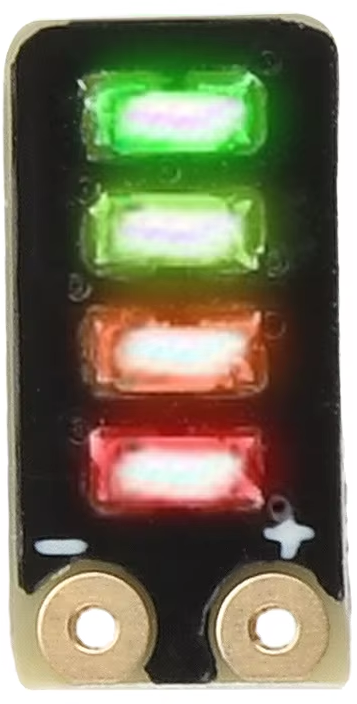
 Design with Battery Indicator SMD in Cirkit Designer
Introduction
The Battery Indicator SMD is a compact surface-mount device designed to visually display the charge level of a battery. It typically uses LED lights to indicate various states, such as charging, fully charged, or low battery. This component is widely used in portable electronics, battery management systems, and consumer devices to provide users with a quick and intuitive understanding of battery status.
Explore Projects Built with Battery Indicator SMD
 Open Project in Cirkit Designer
 Open Project in Cirkit Designer
 Open Project in Cirkit Designer
 Open Project in Cirkit Designer
Explore Projects Built with Battery Indicator SMD
Open Project in Cirkit DesignerOpen Project in Cirkit DesignerOpen Project in Cirkit DesignerOpen Project in Cirkit DesignerCommon Applications and Use Cases
- Portable electronic devices (e.g., smartphones, tablets, and power banks)
- Battery management systems in electric vehicles
- Wearable devices and IoT gadgets
- Emergency lighting systems
- Solar-powered devices
Technical Specifications
Key Technical Details
| Parameter | Value |
|---|---|
| Operating Voltage | 2.5V to 5.5V |
| Operating Current | Typically 10mA to 20mA |
| LED Output | Multi-color (e.g., red, green, blue) |
| Battery Voltage Range | 3.0V to 4.2V (typical for Li-ion) |
| Package Type | SMD (Surface-Mount Device) |
| Operating Temperature | -40°C to +85°C |
Pin Configuration and Descriptions
| Pin Number | Pin Name | Description |
|---|---|---|
| 1 | VCC | Power supply input (2.5V to 5.5V) |
| 2 | GND | Ground connection |
| 3 | BAT_IN | Battery voltage input for monitoring |
| 4 | LED1 | LED output for low battery indication (e.g., red) |
| 5 | LED2 | LED output for charging indication (e.g., yellow) |
| 6 | LED3 | LED output for fully charged indication (e.g., green) |
Usage Instructions
How to Use the Component in a Circuit
- Power Supply: Connect the
VCCpin to a regulated power source (2.5V to 5.5V) and theGNDpin to the ground of the circuit. - Battery Connection: Connect the
BAT_INpin to the positive terminal of the battery being monitored. Ensure the battery voltage is within the supported range (e.g., 3.0V to 4.2V for Li-ion batteries). - LED Outputs: Connect the
LED1,LED2, andLED3pins to the cathodes of the respective LEDs. The anodes of the LEDs should be connected to the power supply through appropriate current-limiting resistors (e.g., 330Ω for 5V operation). - Resistor Selection: Calculate the resistor value for each LED using Ohm's Law:
[ R = \frac{V_{supply} - V_{LED}}{I_{LED}} ]
where ( V_{supply} ) is the supply voltage, ( V_{LED} ) is the forward voltage of the LED, and ( I_{LED} ) is the desired current through the LED.
Important Considerations and Best Practices
- Voltage Compatibility: Ensure the battery voltage is within the supported range of the component to avoid incorrect readings or damage.
- Thermal Management: If the component operates in a high-temperature environment, ensure proper heat dissipation to maintain reliability.
- LED Brightness: Use appropriate resistors to control the brightness of the LEDs and prevent excessive current draw.
- PCB Design: Place the Battery Indicator SMD close to the battery terminals to minimize voltage drops due to trace resistance.
Example Code for Arduino UNO
The Battery Indicator SMD can be interfaced with an Arduino UNO to monitor battery voltage and control LEDs. Below is an example code snippet:
// Define pin connections for LEDs
const int ledLow = 3;    // LED1 (Low battery)
const int ledCharging = 4; // LED2 (Charging)
const int ledFull = 5;   // LED3 (Fully charged)

// Define the analog input pin for battery voltage
const int batteryPin = A0;

// Voltage thresholds (adjust based on battery type)
const float lowBatteryThreshold = 3.2;  // Low battery voltage (in volts)
const float fullBatteryThreshold = 4.1; // Fully charged voltage (in volts)

void setup() {
  // Initialize LED pins as outputs
  pinMode(ledLow, OUTPUT);
  pinMode(ledCharging, OUTPUT);
  pinMode(ledFull, OUTPUT);

  // Initialize serial communication for debugging
  Serial.begin(9600);
}

void loop() {
  // Read the battery voltage (scaled to 0-5V by Arduino ADC)
  int analogValue = analogRead(batteryPin);
  float batteryVoltage = (analogValue / 1023.0) * 5.0;

  // Print the battery voltage to the Serial Monitor
  Serial.print("Battery Voltage: ");
  Serial.println(batteryVoltage);

  // Determine battery status and control LEDs
  if (batteryVoltage < lowBatteryThreshold) {
    digitalWrite(ledLow, HIGH);       // Turn on low battery LED
    digitalWrite(ledCharging, LOW);  // Turn off charging LED
    digitalWrite(ledFull, LOW);      // Turn off full battery LED
  } else if (batteryVoltage < fullBatteryThreshold) {
    digitalWrite(ledLow, LOW);       // Turn off low battery LED
    digitalWrite(ledCharging, HIGH); // Turn on charging LED
    digitalWrite(ledFull, LOW);      // Turn off full battery LED
  } else {
    digitalWrite(ledLow, LOW);       // Turn off low battery LED
    digitalWrite(ledCharging, LOW);  // Turn off charging LED
    digitalWrite(ledFull, HIGH);     // Turn on full battery LED
  }

  // Delay for stability
  delay(500);
}
Troubleshooting and FAQs
Common Issues and Solutions
LEDs Not Lighting Up:
- Cause: Incorrect resistor values or loose connections.
- Solution: Verify the resistor values and ensure all connections are secure.
Incorrect Battery Status Indication:
- Cause: Battery voltage outside the supported range or incorrect wiring.
- Solution: Check the battery voltage and ensure proper wiring of the
BAT_INpin.
Overheating:
- Cause: Excessive current draw or high ambient temperature.
- Solution: Use appropriate resistors for LEDs and ensure adequate ventilation.
Flickering LEDs:
- Cause: Unstable power supply or loose connections.
- Solution: Use a stable power source and check all connections.
FAQs
Can this component be used with batteries other than Li-ion?
Yes, but ensure the battery voltage range matches the supported input range of the component.What is the maximum current the LEDs can handle?
The maximum current depends on the LEDs used. Typically, standard SMD LEDs can handle up to 20mA.Can I use this component with a 3.3V microcontroller?
Yes, the component operates within a 2.5V to 5.5V range, making it compatible with 3.3V systems.Do I need external components to use this device?
Yes, you will need current-limiting resistors for the LEDs and possibly a voltage divider for precise battery voltage monitoring.