How to Use Bus I2C: Examples, Pinouts, and Specs
Introduction
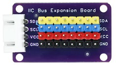
The Bus I2C (Inter-Integrated Circuit) by Chino is a versatile, multi-master, multi-slave, packet-switched, single-ended serial communication bus. It is widely used in embedded systems to connect low-speed devices such as sensors, EEPROMs, real-time clocks, and microcontrollers. The I2C bus is known for its simplicity and efficiency, requiring only two wires for communication: a data line (SDA) and a clock line (SCL).
Explore Projects Built with Bus I2C
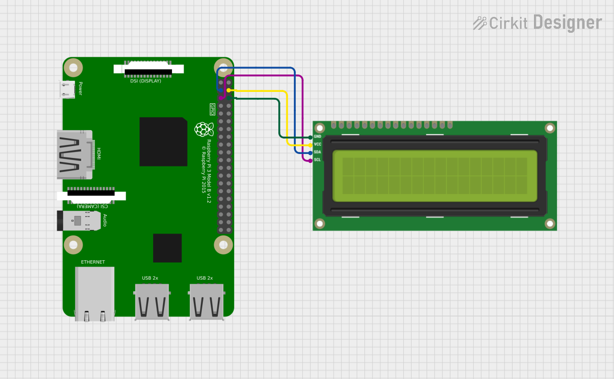
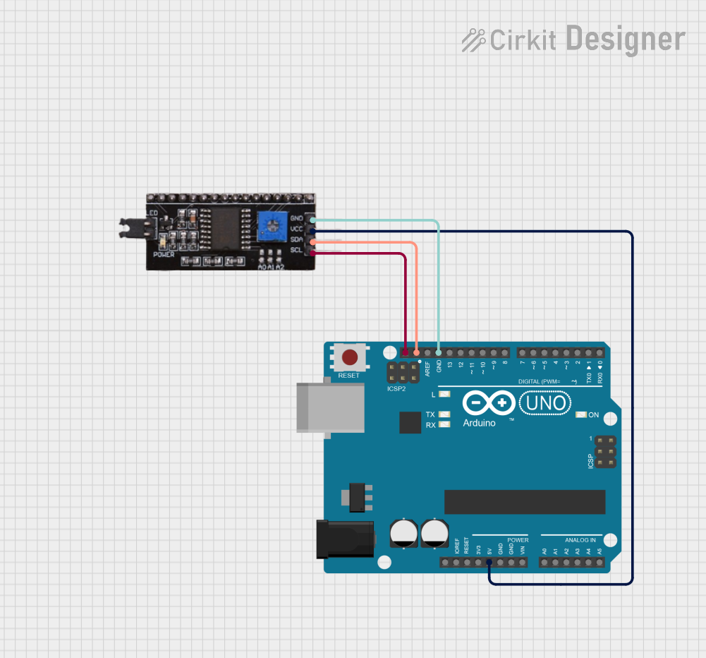

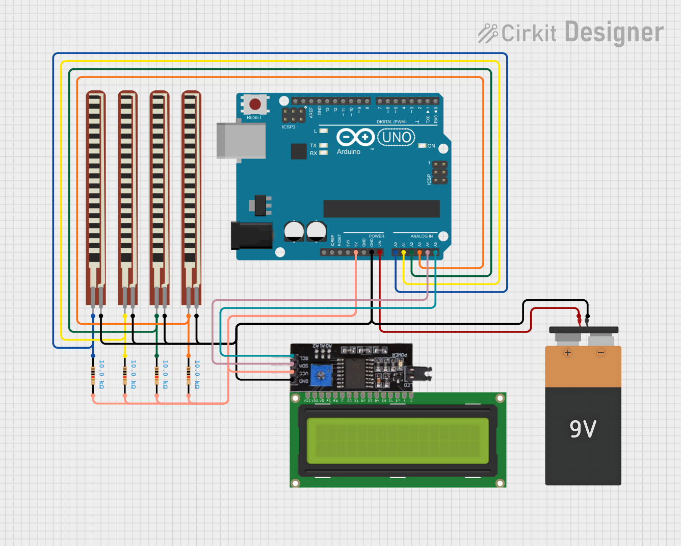
Explore Projects Built with Bus I2C
Common Applications and Use Cases
- Communication between microcontrollers and peripheral devices (e.g., sensors, displays).
- Reading and writing data to EEPROMs or real-time clocks.
- Interfacing with ADCs (Analog-to-Digital Converters) and DACs (Digital-to-Analog Converters).
- Connecting multiple devices on the same bus in embedded systems.
Technical Specifications
The following table outlines the key technical details of the Chino I2C bus:
| Parameter | Specification |
|---|---|
| Communication Type | Serial, synchronous |
| Number of Wires | 2 (SDA - Serial Data, SCL - Serial Clock) |
| Voltage Levels | 3.3V or 5V (depending on the system) |
| Data Rate | Standard Mode: 100 kbps, Fast Mode: 400 kbps |
| Maximum Devices | 127 devices (7-bit addressing) |
| Pull-Up Resistors | Required on SDA and SCL lines (typically 4.7kΩ to 10kΩ) |
| Protocol Features | Multi-master, multi-slave, collision detection |
Pin Configuration and Descriptions
The I2C bus does not have a fixed pinout, as it is implemented on microcontrollers or devices with configurable pins. However, the two essential lines are:
| Pin Name | Description |
|---|---|
| SDA | Serial Data Line: Transfers data between devices. Requires a pull-up resistor. |
| SCL | Serial Clock Line: Synchronizes data transfer. Requires a pull-up resistor. |
Usage Instructions
How to Use the I2C Bus in a Circuit
- Connect the SDA and SCL Lines:
- Connect the SDA and SCL pins of all devices on the bus.
- Use pull-up resistors (typically 4.7kΩ to 10kΩ) on both lines to ensure proper signal levels.
- Set the Voltage Level:
- Ensure all devices on the bus operate at the same voltage level (e.g., 3.3V or 5V).
- Assign Unique Addresses:
- Each device on the I2C bus must have a unique 7-bit or 10-bit address.
- Configure the Master Device:
- The master device (e.g., a microcontroller) initiates communication and controls the clock signal.
- Write or Read Data:
- Use the master device to send commands or request data from slave devices.
Important Considerations and Best Practices
- Pull-Up Resistors: Ensure proper pull-up resistors are used on the SDA and SCL lines to maintain signal integrity.
- Bus Length: Keep the bus length short to minimize signal degradation and interference.
- Address Conflicts: Avoid address conflicts by verifying that all devices have unique addresses.
- Clock Speed: Ensure all devices on the bus support the selected clock speed (e.g., 100 kbps or 400 kbps).
Example: Using I2C with Arduino UNO
Below is an example of how to use the I2C bus to communicate with a sensor using an Arduino UNO:
#include <Wire.h> // Include the Wire library for I2C communication

#define SENSOR_ADDRESS 0x40 // Replace with the I2C address of your sensor

void setup() {
  Wire.begin(); // Initialize the I2C bus
  Serial.begin(9600); // Start serial communication for debugging
}

void loop() {
  Wire.beginTransmission(SENSOR_ADDRESS); // Start communication with the sensor
  Wire.write(0x00); // Send a command to the sensor (e.g., read data)
  Wire.endTransmission(); // End the transmission

  Wire.requestFrom(SENSOR_ADDRESS, 2); // Request 2 bytes of data from the sensor
  if (Wire.available() == 2) { // Check if 2 bytes are available
    int data = Wire.read() << 8 | Wire.read(); // Combine the two bytes into a single value
    Serial.println(data); // Print the data to the serial monitor
  }

  delay(1000); // Wait for 1 second before the next reading
}
Troubleshooting and FAQs
Common Issues and Solutions
No Communication on the Bus:
- Cause: Missing or incorrect pull-up resistors.
- Solution: Verify that pull-up resistors (4.7kΩ to 10kΩ) are connected to the SDA and SCL lines.
Address Conflicts:
- Cause: Two devices on the bus have the same address.
- Solution: Check the datasheets of all devices and configure unique addresses.
Data Corruption:
- Cause: Excessive bus length or noise interference.
- Solution: Shorten the bus length and ensure proper grounding.
Clock Stretching Issues:
- Cause: Slave device holding the clock line low for too long.
- Solution: Verify that all devices support the selected clock speed and protocol.
FAQs
Q: Can I connect devices with different voltage levels on the same I2C bus?
A: No, all devices must operate at the same voltage level. Use level shifters if necessary.Q: How many devices can I connect to the I2C bus?
A: Up to 127 devices can be connected using 7-bit addressing.Q: What happens if two masters try to communicate at the same time?
A: The I2C protocol includes collision detection to handle such scenarios. One master will back off.Q: Do I need external pull-up resistors if my microcontroller has internal ones?
A: External pull-up resistors are recommended for reliable operation, as internal ones may not provide sufficient pull-up strength.
This documentation provides a comprehensive guide to understanding and using the Chino I2C bus in embedded systems.