How to Use Traffic Light: Examples, Pinouts, and Specs
Introduction
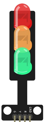
A Traffic Light module is an electronic component that simulates a standard traffic light system. It is commonly used in educational settings to teach basic electronics and programming, as well as in hobbyist projects to control traffic in model setups. The module typically consists of three LEDs (Red, Yellow, and Green) that can be individually controlled to replicate the operation of real-world traffic signals.
Explore Projects Built with Traffic Light
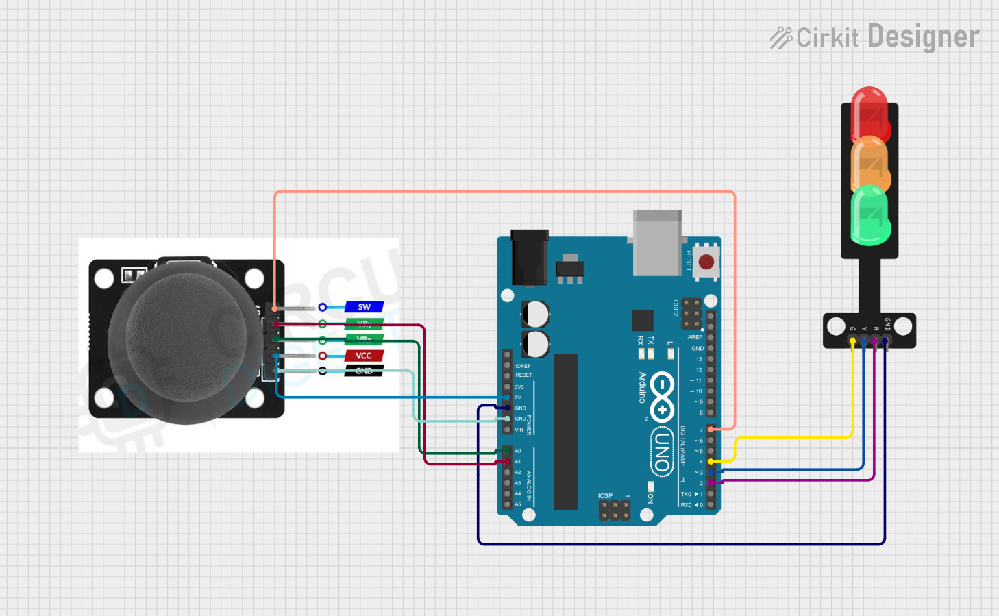
Explore Projects Built with Traffic Light
Common Applications and Use Cases
- Educational projects to demonstrate traffic control systems
- Model traffic systems for hobbyist railway or road setups
- Interactive art installations
- Basic robotics and automation projects
Technical Specifications
Key Technical Details
- Operating Voltage: Typically 3.3V to 5V
- Current Rating: 20mA per LED (typical)
- Power Ratings: Approximately 0.06W per LED
Pin Configuration and Descriptions
| Pin Number | Description | Notes |
|---|---|---|
| 1 | Red LED Anode | Connect to digital output pin |
| 2 | Yellow LED Anode | Connect to digital output pin |
| 3 | Green LED Anode | Connect to digital output pin |
| 4 | Common Cathode | Connect to GND |
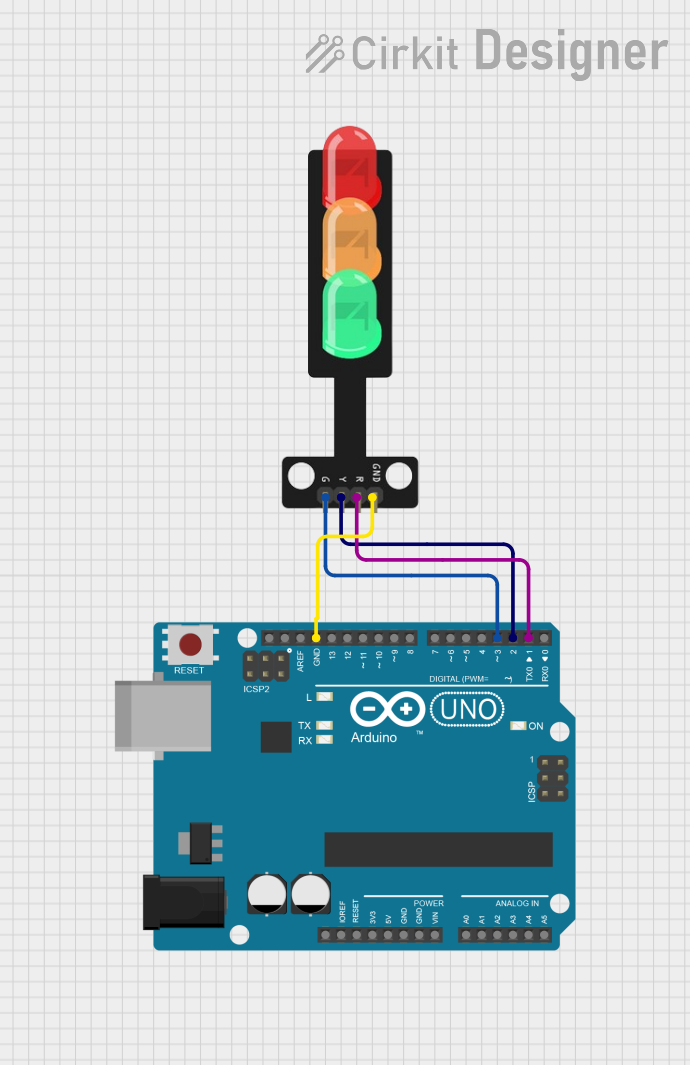
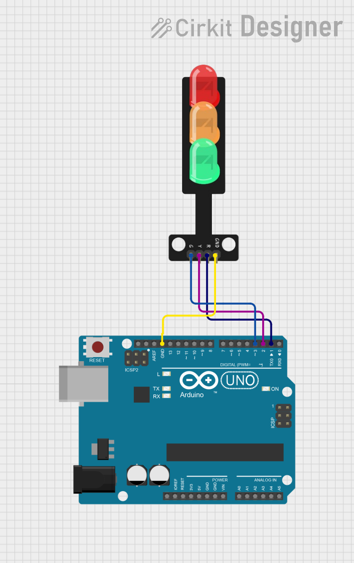
Usage Instructions
How to Use the Component in a Circuit
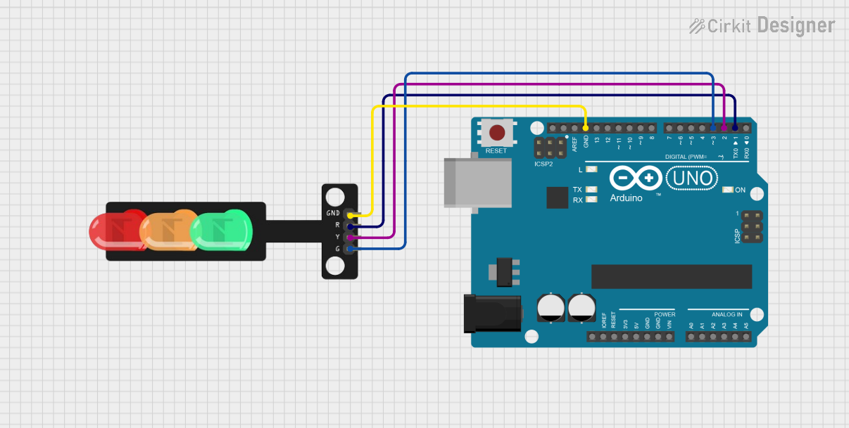
- Connect the common cathode pin to the ground (GND) of your power source or microcontroller.
- Connect each anode pin of the LEDs to a digital output pin on your microcontroller through a current-limiting resistor (typically 220 ohms for 5V operation).
- Ensure that the power supply voltage does not exceed the maximum rating of the LEDs to prevent damage.
Important Considerations and Best Practices
- Always use current-limiting resistors to prevent damage to the LEDs.
- Use pulse-width modulation (PWM) if you need to control the brightness of the LEDs.
- Avoid exposing the LEDs to voltages above their maximum rating.
- Ensure proper polarity when connecting the LEDs to prevent irreversible damage.
Example Code for Arduino UNO
// Define the pin numbers for the LEDs
const int redLED = 10;
const int yellowLED = 9;
const int greenLED = 8;

void setup() {
  // Set the LED pins as outputs
  pinMode(redLED, OUTPUT);
  pinMode(yellowLED, OUTPUT);
  pinMode(greenLED, OUTPUT);
}

void loop() {
  // Red light for 5 seconds
  digitalWrite(redLED, HIGH);
  delay(5000);
  digitalWrite(redLED, LOW);

  // Yellow light for 2 seconds (transition)
  digitalWrite(yellowLED, HIGH);
  delay(2000);
  digitalWrite(yellowLED, LOW);

  // Green light for 5 seconds
  digitalWrite(greenLED, HIGH);
  delay(5000);
  digitalWrite(greenLED, LOW);

  // Yellow light for 2 seconds (transition)
  digitalWrite(yellowLED, HIGH);
  delay(2000);
  digitalWrite(yellowLED, LOW);
}
Troubleshooting and FAQs
Common Issues Users Might Face
- LEDs not lighting up: Check the connections and ensure that the polarity is correct. Also, verify that the current-limiting resistors are in place.
- LEDs too dim or too bright: Adjust the value of the current-limiting resistors. If using a microcontroller, check the code for correct pin assignments and logic levels.
- One or more LEDs are not working: Ensure that the LEDs are not damaged and that the solder joints are secure.
Solutions and Tips for Troubleshooting
- Double-check wiring against the circuit diagram.
- Use a multimeter to verify that each LED is receiving the correct voltage.
- Inspect the LEDs in a dim environment to determine if they are glowing faintly, indicating a potential issue with current flow.
FAQs
Q: Can I use a different voltage supply for the LEDs? A: Yes, but ensure that you adjust the current-limiting resistor values accordingly to prevent damage to the LEDs.
Q: How can I make the transition between lights smoother? A: Implement a PWM fading effect in your code to gradually change the brightness of the LEDs during transitions.
Q: Is it possible to control the Traffic Light module with a remote control? A: Yes, you can use an infrared receiver or a wireless module in conjunction with a microcontroller to receive remote commands and control the Traffic Light module.