How to Use Turbidity: Examples, Pinouts, and Specs
Introduction
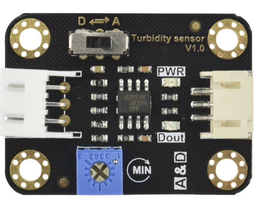
A turbidity sensor measures the cloudiness or haziness of a liquid, which is often caused by suspended particles. It is widely used in water quality testing to assess contamination levels, monitor environmental conditions, and ensure compliance with safety standards. Turbidity sensors are essential in industries such as wastewater treatment, aquaculture, beverage production, and environmental monitoring.
Explore Projects Built with Turbidity
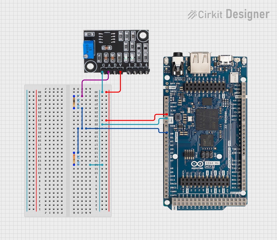
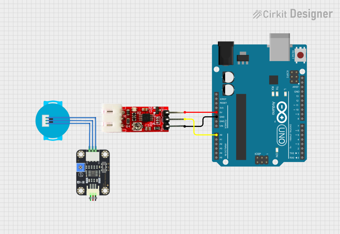
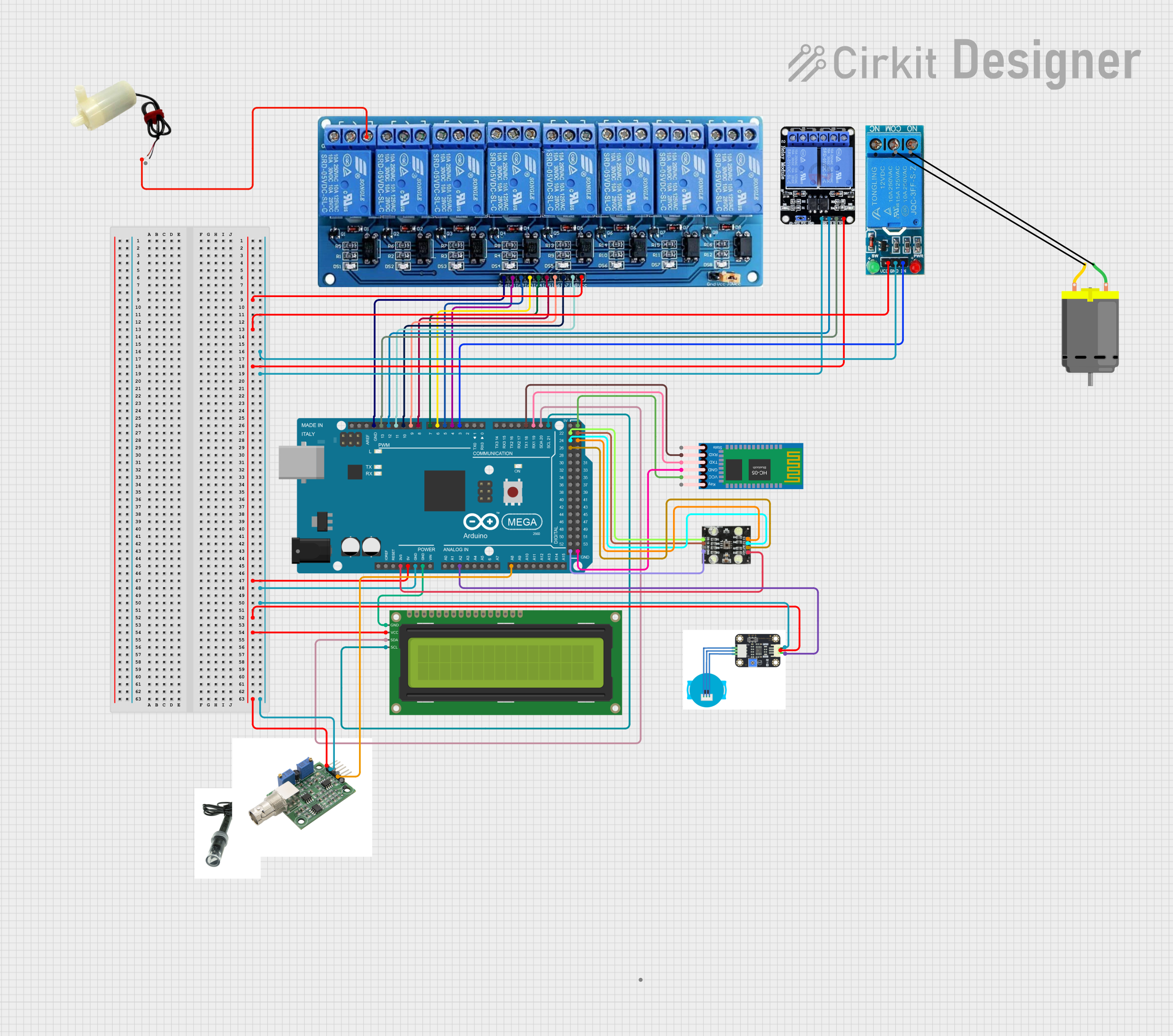
Explore Projects Built with Turbidity
Technical Specifications
Below are the key technical details and pin configuration for a typical turbidity sensor:
Key Technical Details
- Operating Voltage: 5V DC
- Output Signal: Analog (0-4.5V) and Digital (High/Low)
- Current Consumption: ≤ 40mA
- Measurement Range: 0 to 1000 NTU (Nephelometric Turbidity Units)
- Response Time: ≤ 500ms
- Operating Temperature: -30°C to 80°C
- Storage Temperature: -10°C to 80°C
- Connector Type: 4-pin interface (VCC, GND, A0, D0)
Pin Configuration and Descriptions
| Pin | Name | Description |
|---|---|---|
| 1 | VCC | Power supply input (5V DC). |
| 2 | GND | Ground connection. |
| 3 | A0 | Analog output pin. Provides a voltage proportional to the turbidity level. |
| 4 | D0 | Digital output pin. Outputs HIGH or LOW based on a user-defined threshold. |
Usage Instructions
How to Use the Component in a Circuit
- Power the Sensor: Connect the VCC pin to a 5V power source and the GND pin to ground.
- Read Analog Output: Connect the A0 pin to an analog input pin on a microcontroller (e.g., Arduino) to measure the turbidity level as a voltage.
- Set Digital Threshold: Use the onboard potentiometer to adjust the threshold for the digital output. The D0 pin will output HIGH when the turbidity exceeds the threshold and LOW otherwise.
- Calibrate the Sensor: For accurate measurements, calibrate the sensor using a known turbidity standard (e.g., distilled water for 0 NTU).
Important Considerations and Best Practices
- Avoid Air Bubbles: Ensure the sensor is fully submerged in the liquid without air bubbles, as they can affect readings.
- Clean the Sensor: Regularly clean the sensor to remove deposits or fouling that may interfere with measurements.
- Use in Stable Conditions: Minimize vibrations or rapid liquid movement to improve measurement accuracy.
- Temperature Compensation: If precise measurements are required, consider compensating for temperature variations, as they can affect sensor performance.
Example Code for Arduino UNO
Below is an example of how to interface a turbidity sensor with an Arduino UNO to read both analog and digital outputs:
// Turbidity Sensor Example Code for Arduino UNO
// Reads analog and digital outputs from the sensor and displays the results
// on the Serial Monitor.

const int analogPin = A0;  // Analog output pin connected to A0 on Arduino
const int digitalPin = 2;  // Digital output pin connected to D2 on Arduino

void setup() {
  Serial.begin(9600);      // Initialize serial communication at 9600 baud
  pinMode(digitalPin, INPUT); // Set digital pin as input
}

void loop() {
  // Read the analog value from the sensor
  int analogValue = analogRead(analogPin);

  // Convert the analog value to voltage (assuming 5V reference)
  float voltage = analogValue * (5.0 / 1023.0);

  // Read the digital output from the sensor
  int digitalValue = digitalRead(digitalPin);

  // Print the results to the Serial Monitor
  Serial.print("Analog Voltage: ");
  Serial.print(voltage);
  Serial.println(" V");

  Serial.print("Digital Output: ");
  if (digitalValue == HIGH) {
    Serial.println("HIGH (Turbidity above threshold)");
  } else {
    Serial.println("LOW (Turbidity below threshold)");
  }

  delay(1000); // Wait for 1 second before the next reading
}
Troubleshooting and FAQs
Common Issues Users Might Face
Inconsistent Readings:
- Cause: Air bubbles or debris on the sensor.
- Solution: Ensure the sensor is clean and fully submerged without air bubbles.
No Output from the Sensor:
- Cause: Incorrect wiring or insufficient power supply.
- Solution: Double-check the connections and ensure the power supply is 5V DC.
Digital Output Always HIGH or LOW:
- Cause: Incorrect threshold setting.
- Solution: Adjust the potentiometer to set an appropriate threshold.
Analog Output Not Changing:
- Cause: Sensor malfunction or improper calibration.
- Solution: Test the sensor with a known turbidity standard and recalibrate if necessary.
Solutions and Tips for Troubleshooting
- Verify Connections: Ensure all pins are securely connected to the correct terminals.
- Check Power Supply: Use a stable 5V DC power source to avoid fluctuations.
- Inspect the Sensor: Look for physical damage or contamination on the sensor probe.
- Test with Known Standards: Use liquids with known turbidity levels to verify sensor accuracy.
By following this documentation, users can effectively integrate and operate a turbidity sensor in their projects, ensuring reliable and accurate measurements.