How to Use 8 Way Channel Expansion Relay Module 5V Power Supply Optocoupler Isolation Board IIC I2C Communication: Examples, Pinouts, and Specs
Introduction
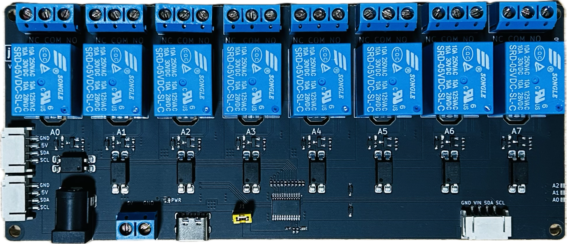
The 8 Way Channel Expansion Relay Module by Songle (Part ID: RELAY) is a versatile and reliable relay module designed for controlling high-power devices using low-power control signals. This module features 8 independent relays, each capable of switching AC or DC loads, and is equipped with optocoupler isolation for enhanced safety and noise immunity. It supports IIC/I2C communication, making it ideal for microcontroller-based projects, including Arduino and Raspberry Pi applications.
Explore Projects Built with 8 Way Channel Expansion Relay Module 5V Power Supply Optocoupler Isolation Board IIC I2C Communication


Explore Projects Built with 8 Way Channel Expansion Relay Module 5V Power Supply Optocoupler Isolation Board IIC I2C Communication
Common Applications and Use Cases
- Home automation systems (e.g., controlling lights, fans, or appliances)
- Industrial automation and control
- Robotics and motor control
- IoT (Internet of Things) projects
- Signal isolation and power switching in embedded systems
Technical Specifications
Key Technical Details
| Parameter | Specification |
|---|---|
| Operating Voltage | 5V DC |
| Trigger Voltage (High) | 4.5V - 5V |
| Trigger Voltage (Low) | 0V - 0.5V |
| Relay Type | Songle SRD-05VDC-SL-C |
| Maximum Load (AC) | 250V AC @ 10A |
| Maximum Load (DC) | 30V DC @ 10A |
| Communication Protocol | IIC/I2C |
| Isolation | Optocoupler isolation for each relay |
| Dimensions | 138mm x 56mm x 18mm |
| Weight | ~120g |
Pin Configuration and Descriptions
Power and Communication Pins
| Pin Name | Description |
|---|---|
| VCC | 5V DC power supply input |
| GND | Ground connection |
| SDA | I2C data line for communication |
| SCL | I2C clock line for communication |
Relay Control Pins
| Pin Name | Description |
|---|---|
| IN1-IN8 | Control signals for relays 1 through 8. A HIGH signal activates the relay. |
Relay Output Terminals
| Terminal Name | Description |
|---|---|
| COM | Common terminal for the relay |
| NO | Normally Open terminal. Connects to COM when the relay is activated. |
| NC | Normally Closed terminal. Connects to COM when the relay is deactivated. |
Usage Instructions
How to Use the Component in a Circuit
- Power the Module: Connect the VCC pin to a 5V DC power source and the GND pin to ground.
- Connect the I2C Lines: Connect the SDA and SCL pins to the corresponding I2C pins on your microcontroller (e.g., Arduino UNO: A4 for SDA, A5 for SCL).
- Control the Relays: Use the I2C protocol to send commands to the module, activating or deactivating the desired relays.
- Connect the Load: Wire the load to the relay terminals (COM, NO, NC) as per your application requirements.
Important Considerations and Best Practices
- Power Supply: Ensure the module is powered with a stable 5V DC supply. Avoid exceeding the voltage rating.
- Isolation: The optocoupler isolation protects your microcontroller from high-voltage spikes. Ensure proper grounding for safety.
- Load Ratings: Do not exceed the maximum load ratings of 250V AC @ 10A or 30V DC @ 10A to prevent damage.
- I2C Address: The module's default I2C address is typically 0x20. Check the datasheet or documentation for address configuration if needed.
- Decoupling Capacitors: Use decoupling capacitors near the power supply pins to reduce noise and improve stability.
Example Code for Arduino UNO
#include <Wire.h> // Include the Wire library for I2C communication

#define RELAY_I2C_ADDRESS 0x20 // Default I2C address of the relay module

void setup() {
  Wire.begin(); // Initialize I2C communication
  Serial.begin(9600); // Initialize serial communication for debugging

  // Turn off all relays at startup
  Wire.beginTransmission(RELAY_I2C_ADDRESS);
  Wire.write(0x00); // Send command to turn off all relays
  Wire.endTransmission();
  Serial.println("Relay module initialized. All relays are OFF.");
}

void loop() {
  // Example: Turn on relay 1
  Wire.beginTransmission(RELAY_I2C_ADDRESS);
  Wire.write(0x01); // Send command to turn on relay 1
  Wire.endTransmission();
  Serial.println("Relay 1 is ON.");
  delay(2000); // Wait for 2 seconds

  // Example: Turn off relay 1
  Wire.beginTransmission(RELAY_I2C_ADDRESS);
  Wire.write(0x00); // Send command to turn off relay 1
  Wire.endTransmission();
  Serial.println("Relay 1 is OFF.");
  delay(2000); // Wait for 2 seconds
}
Troubleshooting and FAQs
Common Issues and Solutions
Relays Not Activating:
- Ensure the module is powered with a stable 5V DC supply.
- Verify the I2C connections (SDA, SCL) and ensure they are correctly wired.
- Check the I2C address of the module and update your code if necessary.
High-Voltage Spikes:
- Use snubber circuits or flyback diodes across inductive loads to suppress voltage spikes.
Noise or Unstable Operation:
- Add decoupling capacitors near the power supply pins.
- Ensure proper grounding and avoid long, unshielded wires for I2C communication.
I2C Communication Errors:
- Check the pull-up resistors on the SDA and SCL lines. Use 4.7kΩ or 10kΩ resistors if needed.
- Verify that no other devices on the I2C bus are using the same address.
FAQs
Q1: Can I use this module with a 3.3V microcontroller?
A1: Yes, but you will need a logic level shifter to safely interface the 3.3V signals with the 5V module.
Q2: How do I change the I2C address of the module?
A2: Refer to the module's datasheet or documentation for instructions on configuring the address using jumpers or solder pads.
Q3: Can I control multiple modules on the same I2C bus?
A3: Yes, as long as each module has a unique I2C address. Configure the addresses accordingly.
Q4: What happens if I exceed the load ratings?
A4: Exceeding the load ratings can damage the relays and pose safety risks. Always stay within the specified limits.