How to Use 4 Way Channel Expansion Relay Module 5V Power Supply Optocoupler Isolation Board IIC I2C Communication: Examples, Pinouts, and Specs
Introduction
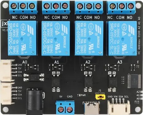
The 4 Way Channel Expansion Relay Module is a versatile electronic component designed for controlling high-power devices using low-power control signals. Manufactured by Songle with the part ID RELAY, this module features four independent relays, each capable of switching AC or DC loads. It is equipped with optocoupler isolation for enhanced safety and noise immunity, making it ideal for applications requiring reliable and isolated control.
Explore Projects Built with 4 Way Channel Expansion Relay Module 5V Power Supply Optocoupler Isolation Board IIC I2C Communication


Explore Projects Built with 4 Way Channel Expansion Relay Module 5V Power Supply Optocoupler Isolation Board IIC I2C Communication
Common Applications and Use Cases
- Home automation systems (e.g., controlling lights, fans, or appliances)
- Industrial automation and motor control
- IoT projects for remote device management
- Robotics and mechatronics
- Prototyping and educational projects
Technical Specifications
Key Technical Details
| Parameter | Specification |
|---|---|
| Operating Voltage | 5V DC |
| Communication Interface | I2C (IIC) |
| Relay Channels | 4 |
| Relay Type | Songle SPDT (Single Pole Double Throw) |
| Maximum Load (AC) | 250V AC @ 10A |
| Maximum Load (DC) | 30V DC @ 10A |
| Optocoupler Isolation | Yes |
| Power Indicator LED | Yes |
| Trigger Signal Voltage | 3.3V or 5V logic |
| Dimensions | 75mm x 55mm x 20mm |
Pin Configuration and Descriptions
Input Pins
| Pin Name | Description |
|---|---|
| VCC | 5V DC power supply input for the module. |
| GND | Ground connection. |
| SDA | I2C data line for communication with a microcontroller. |
| SCL | I2C clock line for communication with a microcontroller. |
Output Terminals (Relay Channels)
| Terminal Name | Description |
|---|---|
| COM | Common terminal for the relay. |
| NO | Normally Open terminal. Connect the load here for default OFF state. |
| NC | Normally Closed terminal. Connect the load here for default ON state. |
Usage Instructions
How to Use the Component in a Circuit
- Power the Module: Connect the VCC pin to a 5V DC power source and the GND pin to ground.
- Connect to a Microcontroller: Use the SDA and SCL pins to interface the module with a microcontroller (e.g., Arduino UNO) via the I2C protocol.
- Load Connections: For each relay channel, connect the load to the COM and either the NO or NC terminal, depending on the desired default state.
- Control the Relays: Send I2C commands from the microcontroller to activate or deactivate the relays.
Important Considerations and Best Practices
- Isolation: Ensure proper isolation between the high-voltage load and the low-voltage control circuit to prevent damage or hazards.
- Power Supply: Use a stable 5V DC power source to avoid erratic relay behavior.
- Load Ratings: Do not exceed the maximum load ratings (250V AC @ 10A or 30V DC @ 10A) to prevent damage to the relays.
- I2C Address: Check the module's default I2C address and ensure it does not conflict with other devices on the same bus.
- Decoupling Capacitors: Add decoupling capacitors near the power pins to reduce noise and improve stability.
Example Code for Arduino UNO
#include <Wire.h> // Include the Wire library for I2C communication

#define RELAY_MODULE_I2C_ADDRESS 0x20 // Default I2C address of the relay module

void setup() {
  Wire.begin(); // Initialize I2C communication
  Serial.begin(9600); // Initialize serial communication for debugging

  // Turn off all relays at startup
  Wire.beginTransmission(RELAY_MODULE_I2C_ADDRESS);
  Wire.write(0x00); // Command to turn off all relays
  Wire.endTransmission();
  Serial.println("Relay module initialized. All relays are OFF.");
}

void loop() {
  // Example: Turn on Relay 1
  Wire.beginTransmission(RELAY_MODULE_I2C_ADDRESS);
  Wire.write(0x01); // Command to turn on Relay 1
  Wire.endTransmission();
  Serial.println("Relay 1 is ON.");
  delay(2000); // Wait for 2 seconds

  // Example: Turn off Relay 1
  Wire.beginTransmission(RELAY_MODULE_I2C_ADDRESS);
  Wire.write(0x00); // Command to turn off Relay 1
  Wire.endTransmission();
  Serial.println("Relay 1 is OFF.");
  delay(2000); // Wait for 2 seconds
}
Troubleshooting and FAQs
Common Issues and Solutions
Relays Not Activating:
- Cause: Insufficient power supply or incorrect wiring.
- Solution: Ensure the VCC pin is connected to a stable 5V DC source and the GND pin is properly grounded.
I2C Communication Fails:
- Cause: Incorrect I2C address or wiring.
- Solution: Verify the module's I2C address and ensure SDA and SCL are connected to the correct pins on the microcontroller.
Erratic Relay Behavior:
- Cause: Electrical noise or unstable power supply.
- Solution: Add decoupling capacitors near the power pins and use a regulated power source.
Load Not Switching Properly:
- Cause: Exceeding the relay's load ratings.
- Solution: Ensure the load does not exceed 250V AC @ 10A or 30V DC @ 10A.
FAQs
Q: Can this module be used with a 3.3V microcontroller?
A: Yes, the module supports 3.3V logic levels for the trigger signals.Q: How do I change the I2C address of the module?
A: Refer to the module's datasheet or manufacturer documentation for instructions on modifying the I2C address.Q: Is it safe to use this module for high-power appliances?
A: Yes, as long as the load does not exceed the specified ratings and proper isolation is maintained.Q: Can I control multiple modules on the same I2C bus?
A: Yes, ensure each module has a unique I2C address to avoid conflicts.