How to Use JST SH1 x8 Male: Examples, Pinouts, and Specs
Introduction
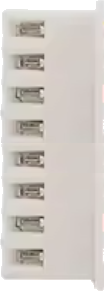
The JST SH1 x8 Male is a compact, 1.0mm pitch connector designed for reliable and space-efficient wire-to-board or wire-to-wire connections in electronic circuits. With 8 pins, it provides multiple connection points, making it ideal for applications requiring compact and precise wiring solutions. Its small form factor and robust design make it a popular choice in consumer electronics, robotics, drones, and other compact devices.
Explore Projects Built with JST SH1 x8 Male


Explore Projects Built with JST SH1 x8 Male
Common Applications
- Connecting sensors, actuators, and modules in compact devices
- Wire-to-board connections in drones and robotics
- Consumer electronics such as cameras, wearables, and handheld devices
- Prototyping and small-scale production circuits
Technical Specifications
The JST SH1 x8 Male connector is designed to meet the needs of compact and high-density electronic systems. Below are its key technical specifications:
| Parameter | Specification |
|---|---|
| Pitch | 1.0mm |
| Number of Pins | 8 |
| Current Rating | 0.5A per pin |
| Voltage Rating | 50V DC |
| Contact Resistance | ≤ 20mΩ |
| Insulation Resistance | ≥ 500MΩ |
| Operating Temperature | -25°C to +85°C |
| Connector Type | Male (Plug) |
| Mounting Style | Wire-to-board or wire-to-wire |
Pin Configuration and Descriptions
The JST SH1 x8 Male connector has 8 pins arranged in a single row with a 1.0mm pitch. Below is the pin configuration:
| Pin Number | Description |
|---|---|
| 1 | Signal/Power Line 1 |
| 2 | Signal/Power Line 2 |
| 3 | Signal/Power Line 3 |
| 4 | Signal/Power Line 4 |
| 5 | Signal/Power Line 5 |
| 6 | Signal/Power Line 6 |
| 7 | Signal/Power Line 7 |
| 8 | Signal/Power Line 8 |
Note: Pin assignments depend on the specific application and circuit design. Always refer to the circuit schematic for proper pin usage.
Usage Instructions
How to Use the JST SH1 x8 Male Connector
Prepare the Wires:
- Strip the insulation from the wires to expose approximately 1-2mm of the conductor.
- Ensure the wires are clean and free of damage.
Crimp the Contacts:
- Use a compatible crimping tool to attach the crimp terminals to the wires.
- Ensure the crimp is secure and that the conductor is properly seated in the terminal.
Insert the Contacts:
- Insert the crimped terminals into the connector housing until they click into place.
- Verify that all terminals are securely locked in the housing.
Connect to the Mating Connector:
- Align the JST SH1 x8 Male connector with the corresponding female connector.
- Gently push the connectors together until they are fully mated.
Secure the Connection:
- If necessary, use additional securing mechanisms (e.g., latches or adhesive) to prevent accidental disconnection.
Important Considerations
- Wire Gauge: Use wires with a gauge compatible with the crimp terminals (typically 28-32 AWG).
- Current and Voltage Limits: Do not exceed the specified current (0.5A per pin) and voltage (50V DC) ratings.
- Environmental Conditions: Avoid exposing the connector to temperatures or humidity levels outside the specified operating range.
- Mating Cycles: The connector is rated for a limited number of mating cycles (typically 50). Minimize unnecessary connections and disconnections to prolong its lifespan.
Example: Connecting to an Arduino UNO
The JST SH1 x8 Male connector can be used to connect sensors or modules to an Arduino UNO. Below is an example of connecting a sensor with an 8-pin JST SH1 connector to the Arduino:
Circuit Diagram
- Pin 1: VCC (5V from Arduino)
- Pin 2: GND (Ground)
- Pin 3: Signal Line 1 (e.g., Sensor Data)
- Pin 4-8: Additional signal lines or unused
Sample Code
// Example code for reading data from a sensor connected via JST SH1 x8 Male
// Pin 3 of the connector is used for sensor data input

const int sensorPin = A0; // Connect Pin 3 of JST SH1 to Arduino A0

void setup() {
  Serial.begin(9600); // Initialize serial communication at 9600 baud
  pinMode(sensorPin, INPUT); // Set sensor pin as input
}

void loop() {
  int sensorValue = analogRead(sensorPin); // Read analog value from sensor
  Serial.print("Sensor Value: ");
  Serial.println(sensorValue); // Print sensor value to Serial Monitor
  delay(500); // Wait for 500ms before the next reading
}
Note: Ensure proper wiring and verify the sensor's pinout before connecting to the Arduino.
Troubleshooting and FAQs
Common Issues
Loose Connections:
- Cause: Improper crimping or incomplete insertion of terminals into the housing.
- Solution: Re-crimp the terminals and ensure they are fully seated in the housing.
Intermittent Signal Loss:
- Cause: Damaged wires or poor contact between the male and female connectors.
- Solution: Inspect the wires and connectors for damage. Replace if necessary.
Overheating:
- Cause: Exceeding the current rating of 0.5A per pin.
- Solution: Reduce the current load or distribute the current across multiple pins.
Connector Does Not Fit:
- Cause: Mismatched connector type or incorrect alignment.
- Solution: Verify that the mating connector is a JST SH1 x8 Female and align properly before connecting.
FAQs
Q1: Can I use the JST SH1 x8 Male connector for high-power applications?
A1: No, the connector is rated for a maximum current of 0.5A per pin and a voltage of 50V DC. It is not suitable for high-power applications.
Q2: What tools are required for crimping the terminals?
A2: A compatible crimping tool designed for JST SH1 terminals is required. Using the correct tool ensures a secure and reliable connection.
Q3: Can I reuse the connector after disassembling it?
A3: While it is possible to remove and reuse the terminals, repeated disassembly may weaken the locking mechanism. It is recommended to use new terminals for critical applications.
Q4: Are there pre-assembled cables available for this connector?
A4: Yes, pre-assembled cables with JST SH1 x8 connectors are available from various suppliers, which can save time during prototyping and assembly.