How to Use Thumb Joystick: Examples, Pinouts, and Specs

Introduction
The Thumb Joystick (Manufacturer: Seeed Studio, Part ID: 101020028) is a compact, handheld input device designed for precise directional control and movement in electronic systems. It features a two-axis analog stick and a built-in push button, making it ideal for applications requiring intuitive navigation or control. The joystick is commonly used in gaming controllers, robotic systems, menu navigation, and other interactive projects.
Explore Projects Built with Thumb Joystick


Explore Projects Built with Thumb Joystick
Common Applications
- Gaming controllers for directional input
- Robotic control systems
- Menu navigation in embedded systems
- Camera gimbal control
- DIY electronics and Arduino projects
Technical Specifications
The following table outlines the key technical details of the Thumb Joystick:
| Parameter | Specification |
|---|---|
| Manufacturer | Seeed Studio |
| Part ID | 101020028 |
| Operating Voltage | 3.3V to 5V |
| Output Type | Analog (X and Y axes), Digital (Button) |
| X-Axis Output Range | 0V to VCC (centered at ~VCC/2) |
| Y-Axis Output Range | 0V to VCC (centered at ~VCC/2) |
| Button Output | Digital (Active Low) |
| Dimensions | 40mm x 26mm x 32mm |
| Interface | 5-pin header (GND, VCC, VRx, VRy, SW) |
Pin Configuration and Descriptions
The Thumb Joystick has a 5-pin interface. The table below describes each pin:
| Pin | Name | Description |
|---|---|---|
| 1 | GND | Ground connection |
| 2 | VCC | Power supply (3.3V to 5V) |
| 3 | VRx | Analog output for X-axis movement |
| 4 | VRy | Analog output for Y-axis movement |
| 5 | SW | Digital output for the push button (Active Low) |
Usage Instructions
Connecting the Thumb Joystick
To use the Thumb Joystick in a circuit, follow these steps:
- Power Supply: Connect the
VCCpin to a 3.3V or 5V power source and theGNDpin to ground. - Analog Outputs: Connect the
VRxandVRypins to the analog input pins of your microcontroller (e.g., Arduino). - Button Output: Connect the
SWpin to a digital input pin of your microcontroller. Use a pull-up resistor if necessary.
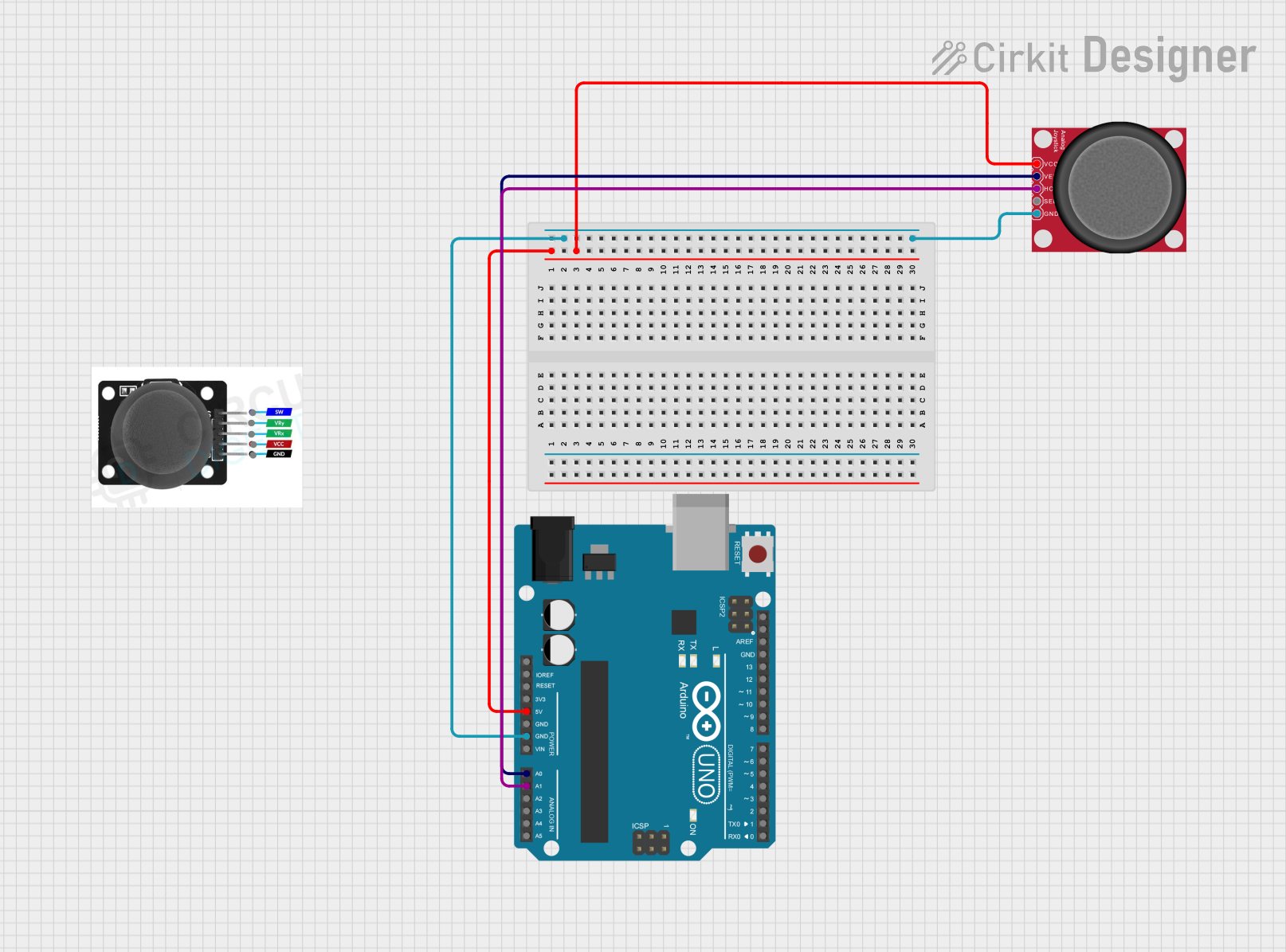
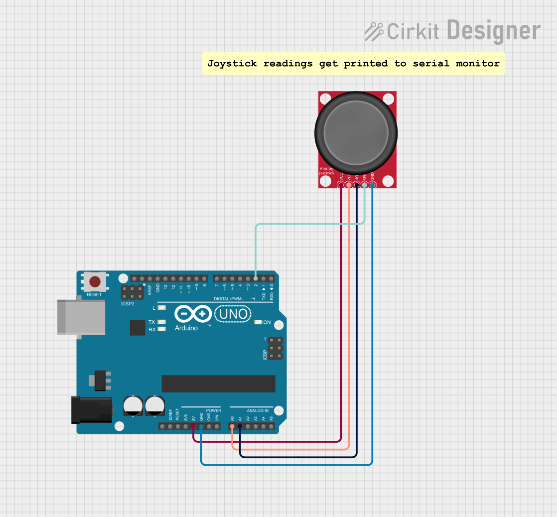
Example Circuit with Arduino UNO
Below is an example of how to connect the Thumb Joystick to an Arduino UNO:
GND→ GND on ArduinoVCC→ 5V on ArduinoVRx→ A0 on ArduinoVRy→ A1 on ArduinoSW→ D2 on Arduino
Sample Arduino Code
The following Arduino sketch reads the joystick's X and Y positions and detects button presses:
// Pin definitions
const int VRxPin = A0; // X-axis analog output
const int VRyPin = A1; // Y-axis analog output
const int SWPin = 2;   // Push button digital output

void setup() {
  // Initialize serial communication for debugging
  Serial.begin(9600);

  // Configure the button pin as input with internal pull-up resistor
  pinMode(SWPin, INPUT_PULLUP);
}

void loop() {
  // Read the X and Y axis values (0 to 1023)
  int xValue = analogRead(VRxPin);
  int yValue = analogRead(VRyPin);

  // Read the button state (LOW when pressed)
  int buttonState = digitalRead(SWPin);

  // Print the joystick values to the Serial Monitor
  Serial.print("X: ");
  Serial.print(xValue);
  Serial.print(" | Y: ");
  Serial.print(yValue);
  Serial.print(" | Button: ");
  Serial.println(buttonState == LOW ? "Pressed" : "Released");

  // Add a small delay for stability
  delay(100);
}
Important Considerations
- Voltage Compatibility: Ensure the joystick's operating voltage matches your microcontroller's input voltage (3.3V or 5V).
- Debouncing: If the button output is noisy, consider implementing software debouncing.
- Calibration: The joystick's center position may not output exactly half of the supply voltage. Calibrate the readings in your code if necessary.
Troubleshooting and FAQs
Common Issues and Solutions
No Output from the Joystick
- Cause: Incorrect wiring or loose connections.
- Solution: Double-check all connections, ensuring the
VCCandGNDpins are properly connected.
Button Not Detected
- Cause: Missing pull-up resistor or incorrect pin configuration.
- Solution: Use the
INPUT_PULLUPmode in your code or add an external pull-up resistor.
Inconsistent Analog Readings
- Cause: Electrical noise or poor power supply.
- Solution: Add decoupling capacitors near the joystick's power pins to stabilize the voltage.
Joystick Center Position Not Accurate
- Cause: Manufacturing tolerances.
- Solution: Calibrate the joystick in your software by measuring the actual center values.
FAQs
Q: Can I use the Thumb Joystick with a Raspberry Pi?
A: Yes, the joystick can be used with a Raspberry Pi. Connect the analog outputs (VRx and VRy) to an ADC (Analog-to-Digital Converter) since the Raspberry Pi lacks built-in analog input pins.
Q: What is the lifespan of the joystick?
A: The joystick is designed for long-term use, but its lifespan depends on the operating environment and frequency of use. Handle it gently to maximize durability.
Q: Can I use the joystick for 360-degree control?
A: Yes, the joystick provides full 360-degree analog control, making it suitable for applications like robotic arms or camera gimbals.
Q: Is the push button necessary for operation?
A: No, the push button is optional and can be left unconnected if not required for your application.