How to Use tyrox board: Examples, Pinouts, and Specs
Introduction
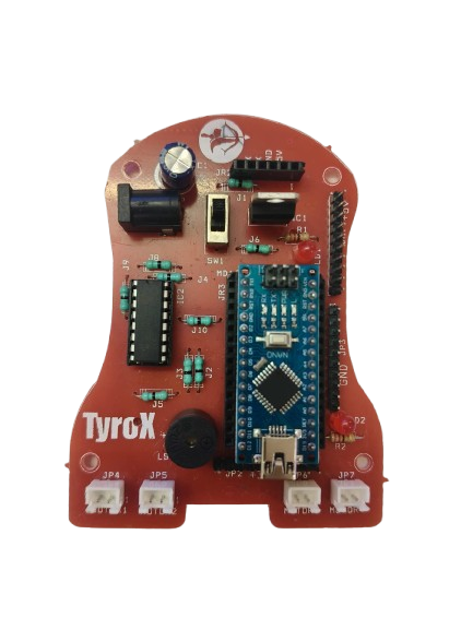
The Tyrox board is a versatile prototyping board designed for building and testing electronic circuits. It features a grid of holes that allow users to insert components and connect them using wires or solder. This flexibility makes it an essential tool for engineers, hobbyists, and students working on circuit design and experimentation. The Tyrox board is ideal for creating temporary or semi-permanent circuits before committing to a final printed circuit board (PCB) design.
Explore Projects Built with tyrox board

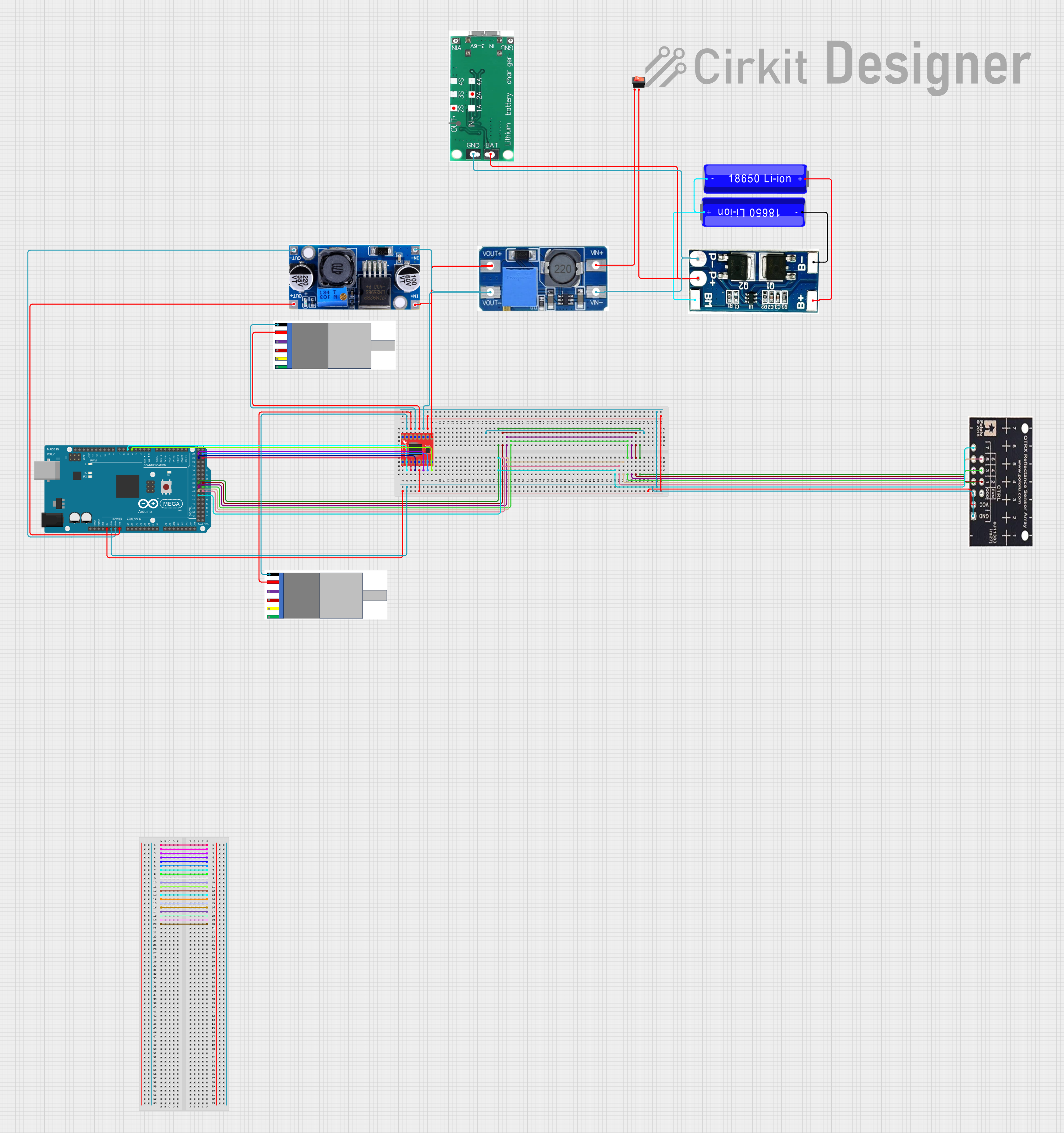
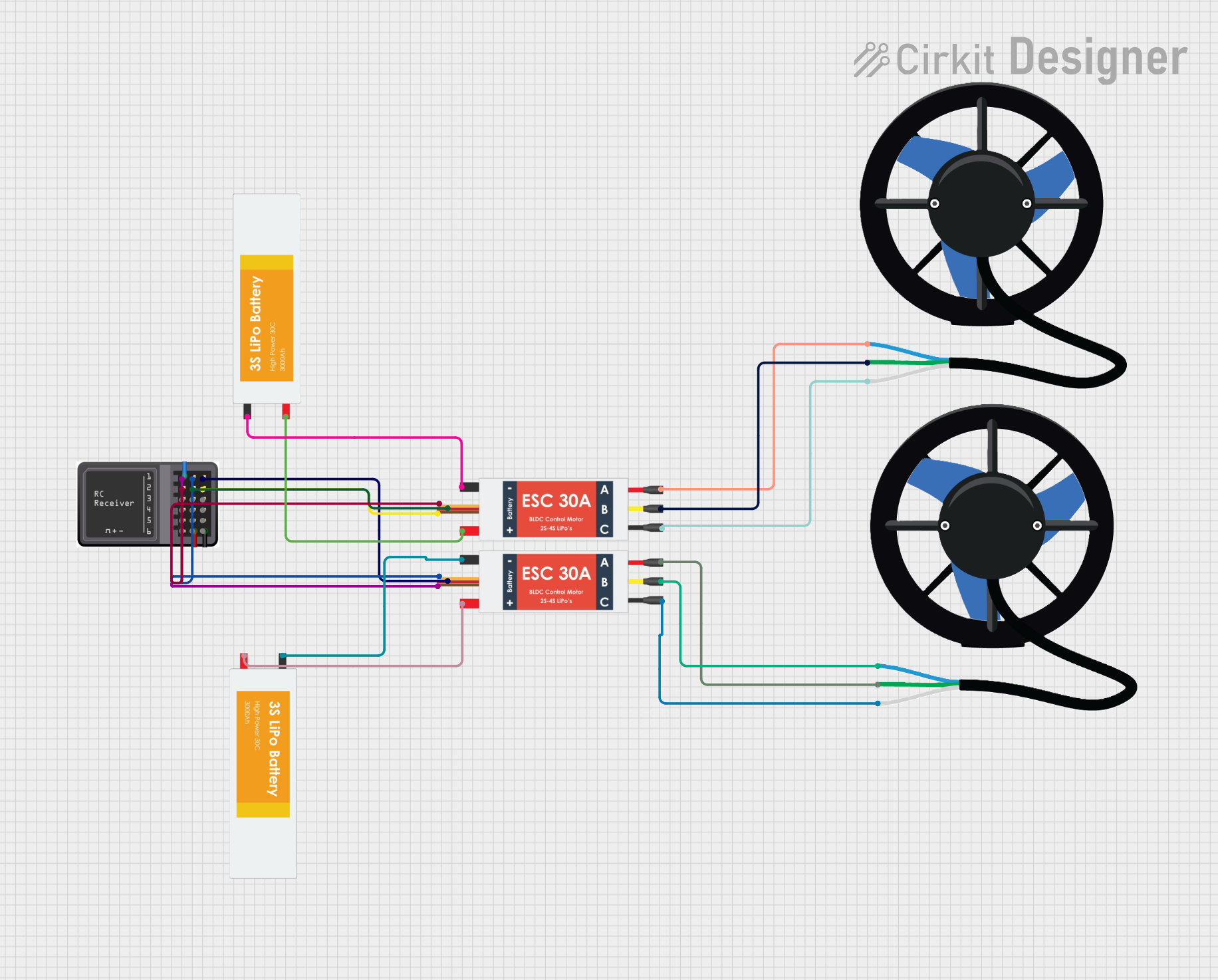

Explore Projects Built with tyrox board
Common Applications and Use Cases
- Rapid prototyping of electronic circuits
- Educational projects and learning circuit design
- Testing and debugging new circuit designs
- Building semi-permanent circuits for hobby projects
- Experimenting with microcontroller-based systems, such as Arduino or Raspberry Pi
Technical Specifications
The Tyrox board is available in various sizes and configurations to suit different project requirements. Below are the general technical specifications:
| Specification | Details |
|---|---|
| Material | FR4 (fiberglass-reinforced epoxy laminate) |
| Hole Grid Size | 2.54 mm (0.1 inch) pitch |
| Board Thickness | 1.6 mm |
| Hole Diameter | 1.0 mm (suitable for standard through-hole components) |
| Copper Layer | Single-sided or double-sided (varies by model) |
| Solder Mask | Optional (green, blue, or other colors depending on the model) |
| Dimensions | Available in multiple sizes (e.g., 5x7 cm, 7x9 cm, 10x15 cm) |
| Compatibility | Supports standard DIP (Dual Inline Package) components and connectors |
Pin Configuration and Descriptions
The Tyrox board does not have predefined pins, as it is a general-purpose prototyping board. However, the grid layout allows for flexible placement of components and connections. Below is a description of the key features:
| Feature | Description |
|---|---|
| Grid Holes | Uniformly spaced holes for inserting components and wires |
| Power Rails | Some models include dedicated power rails for easy power distribution |
| Copper Traces | Predefined traces on some models to simplify common connections |
| Mounting Holes | Holes for securing the board to enclosures or workbenches |
Usage Instructions
How to Use the Tyrox Board in a Circuit
- Plan Your Circuit: Sketch the circuit diagram and decide the placement of components on the board.
- Insert Components: Place through-hole components (e.g., resistors, capacitors, ICs) into the grid holes.
- Connect Components:
- For temporary connections, use jumper wires to link components.
- For permanent connections, solder the component leads to the copper pads.
- Power Distribution: Use the power rails (if available) to distribute power to the circuit.
- Test the Circuit: Verify the functionality of the circuit using a multimeter or oscilloscope.
Important Considerations and Best Practices
- Avoid Overheating: When soldering, avoid overheating the pads to prevent damage to the board.
- Use Insulated Wires: For jumper connections, use insulated wires to prevent accidental short circuits.
- Label Connections: Label key connections on the board for easier debugging and modifications.
- Clean the Board: After soldering, clean the board with isopropyl alcohol to remove flux residues.
- Microcontroller Integration: The Tyrox board can be used to prototype circuits for microcontrollers like Arduino. Below is an example of connecting an LED to an Arduino UNO using the Tyrox board.
// Example: Blink an LED using Arduino UNO and Tyrox board
// Connect the LED's anode (long leg) to pin 13 on the Arduino
// Connect the LED's cathode (short leg) to a 220-ohm resistor, then to GND

void setup() {
  pinMode(13, OUTPUT); // Set pin 13 as an output pin
}

void loop() {
  digitalWrite(13, HIGH); // Turn the LED on
  delay(1000);            // Wait for 1 second
  digitalWrite(13, LOW);  // Turn the LED off
  delay(1000);            // Wait for 1 second
}
Troubleshooting and FAQs
Common Issues and Solutions
| Issue | Solution |
|---|---|
| Components not staying in place | Use a small amount of solder to secure components or use a breadboard first. |
| Circuit not functioning as expected | Double-check connections against the circuit diagram. |
| Solder bridges causing short circuits | Use a solder wick or desoldering pump to remove excess solder. |
| Difficulty in tracing connections | Use a multimeter to verify continuity and label key connections. |
FAQs
Can I reuse the Tyrox board after soldering?
- Yes, but desoldering components may damage the copper pads. Use care when removing components.
What is the maximum current the board can handle?
- The current capacity depends on the copper trace thickness. For high-current applications, use thicker wires or external power buses.
Can I use surface-mount components on the Tyrox board?
- The Tyrox board is primarily designed for through-hole components, but surface-mount components can be used with adapter boards or creative soldering techniques.
Is the Tyrox board compatible with Arduino shields?
- No, the Tyrox board is a general-purpose prototyping board and does not have the specific pin layout required for Arduino shields. However, you can manually wire connections to an Arduino.
By following this documentation, users can effectively utilize the Tyrox board for a wide range of prototyping and circuit design projects.