How to Use Bost-Buck Converter: Examples, Pinouts, and Specs
Introduction
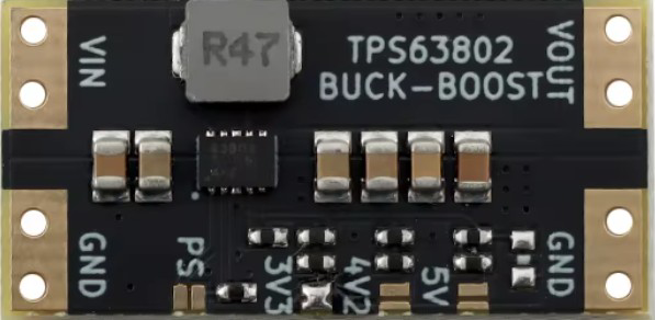
The Bost-Buck Converter (Model: XL63802), manufactured by rwuin, is a highly efficient DC-DC converter designed to step up or step down voltage as required. This versatile component combines the functionality of both boost and buck converters, making it ideal for applications where the input voltage can vary above or below the desired output voltage. Its compact design and high efficiency make it suitable for battery-powered devices, renewable energy systems, and embedded electronics.
Explore Projects Built with Bost-Buck Converter


Explore Projects Built with Bost-Buck Converter
Common Applications
- Battery-powered devices (e.g., portable electronics, wearables)
- Solar power systems and renewable energy applications
- Automotive electronics
- Industrial control systems
- Embedded systems requiring stable voltage regulation
Technical Specifications
Key Technical Details
| Parameter | Value |
|---|---|
| Manufacturer | rwuin |
| Part ID | XL63802 |
| Input Voltage Range | 3.0V to 40V |
| Output Voltage Range | 1.2V to 36V |
| Maximum Output Current | 3A |
| Efficiency | Up to 95% |
| Switching Frequency | 150 kHz |
| Operating Temperature | -40°C to +85°C |
| Package Type | SOP-8 |
Pin Configuration and Descriptions
| Pin Number | Pin Name | Description |
|---|---|---|
| 1 | VIN | Input voltage pin (3.0V to 40V). Connect to the power source. |
| 2 | SW | Switching pin. Connect to the inductor and diode. |
| 3 | GND | Ground pin. Connect to the circuit ground. |
| 4 | FB | Feedback pin. Used to set the output voltage via a resistor divider. |
| 5 | EN | Enable pin. Pull high to enable the converter, low to disable. |
| 6 | COMP | Compensation pin. Connect a capacitor for stability. |
| 7 | NC | No connection. Leave unconnected. |
| 8 | VOUT | Output voltage pin. Connect to the load. |
Usage Instructions
How to Use the XL63802 in a Circuit
- Input Voltage Connection: Connect the input voltage source (3.0V to 40V) to the
VINpin. Ensure the input voltage is within the specified range. - Output Voltage Configuration: Use a resistor divider network connected to the
FBpin to set the desired output voltage. The formula for output voltage is: [ V_{OUT} = V_{REF} \times \left(1 + \frac{R1}{R2}\right) ] where ( V_{REF} ) is typically 1.2V. - Inductor and Diode Selection: Choose an appropriate inductor and Schottky diode based on the input/output voltage and current requirements.
- Enable Pin: Pull the
ENpin high (e.g., connect to VIN) to enable the converter. Pull it low to disable. - Compensation: Connect a capacitor to the
COMPpin to ensure stability during operation. - Output Connection: Connect the load to the
VOUTpin. Ensure the load does not exceed the maximum output current of 3A.
Important Considerations
- Use low Equivalent Series Resistance (ESR) capacitors for input and output filtering to minimize noise.
- Ensure proper heat dissipation by using a heat sink or adequate PCB layout for thermal management.
- Avoid exceeding the maximum input voltage (40V) or output current (3A) to prevent damage.
- Place the inductor and capacitors as close to the IC as possible to reduce electromagnetic interference (EMI).
Example: Using XL63802 with Arduino UNO
The XL63802 can be used to power an Arduino UNO by stepping down a 12V input to 5V. Below is an example circuit and Arduino code to monitor the output voltage.
Circuit Diagram
- Connect a 12V power source to the
VINpin. - Set the output voltage to 5V using a resistor divider on the
FBpin. - Connect the
VOUTpin to the Arduino UNO's 5V input pin.
Arduino Code
// Example code to monitor the output voltage of the XL63802
// using an Arduino UNO's analog input pin.

const int voltagePin = A0; // Analog pin connected to VOUT
const float referenceVoltage = 5.0; // Arduino reference voltage (5V)
const int adcResolution = 1024; // 10-bit ADC resolution

void setup() {
  Serial.begin(9600); // Initialize serial communication
  pinMode(voltagePin, INPUT); // Set the voltage pin as input
}

void loop() {
  int adcValue = analogRead(voltagePin); // Read the ADC value
  float outputVoltage = (adcValue * referenceVoltage) / adcResolution;

  // Print the output voltage to the Serial Monitor
  Serial.print("Output Voltage: ");
  Serial.print(outputVoltage);
  Serial.println(" V");

  delay(1000); // Wait for 1 second before the next reading
}
Troubleshooting and FAQs
Common Issues and Solutions
No Output Voltage
- Cause: The
ENpin is not pulled high. - Solution: Ensure the
ENpin is connected to a high logic level (e.g., VIN).
- Cause: The
Output Voltage is Incorrect
- Cause: Incorrect resistor values in the feedback network.
- Solution: Verify the resistor divider values and recalculate using the formula provided.
Excessive Heat
- Cause: Overloading the converter or insufficient heat dissipation.
- Solution: Reduce the load current or improve thermal management (e.g., add a heat sink).
High Output Ripple
- Cause: Poor capacitor selection or placement.
- Solution: Use low ESR capacitors and place them close to the IC.
FAQs
Q1: Can the XL63802 handle negative input voltages?
A1: No, the XL63802 is designed for positive input voltages only (3.0V to 40V).
Q2: What type of inductor should I use?
A2: Use an inductor with a current rating higher than the maximum output current (3A) and a low DC resistance for better efficiency.
Q3: Can I use the XL63802 for audio applications?
A3: Yes, but ensure proper filtering to minimize noise and interference in sensitive audio circuits.
Q4: Is the XL63802 suitable for battery charging?
A4: Yes, it can be used for battery charging applications, but additional circuitry may be required for proper charge management.
This concludes the documentation for the Bost-Buck Converter (XL63802). For further assistance, refer to the manufacturer's datasheet or contact technical support.