Cirkit Designer Logo
Cirkit Designer
Your all-in-one circuit design IDE
Home / 
Component Documentation

How to Use ICM-20948: Examples, Pinouts, and Specs

Image of ICM-20948
Cirkit Designer LogoDesign with ICM-20948 in Cirkit Designer

Introduction

The ICM-20948 is a highly integrated 9-axis motion tracking device that combines a 3-axis gyroscope, a 3-axis accelerometer, and a 3-axis magnetometer in a single compact package. This sensor is designed for applications requiring precise motion and orientation tracking, such as robotics, drones, augmented reality (AR), virtual reality (VR), and mobile devices. Its small size, low power consumption, and high performance make it an ideal choice for embedded systems and IoT applications.

Explore Projects Built with ICM-20948

Use Cirkit Designer to design, explore, and prototype these projects online. Some projects support real-time simulation. Click "Open Project" to start designing instantly!
Satellite-Based Timing and Navigation System with SDR and Atomic Clock Synchronization
Image of GPS 시스템 측정 구성도_Confirm: A project utilizing ICM-20948 in a practical application
This circuit appears to be a complex system involving power supply management, GPS and timing synchronization, and data communication. It includes a SI-TEX G1 Satellite Compass for GPS data, an XHTF1021 Atomic Rubidium Clock for precise timing, and Ettus USRP B200 units for software-defined radio communication. Power is supplied through various SMPS units and distributed via terminal blocks and DC jacks. Data communication is facilitated by Beelink MINI S12 N95 computers, RS232 splitters, and a 1000BASE-T Media Converter for network connectivity. RF Directional Couplers are used to interface antennas with the USRP units, and the entire system is likely contained within cases for protection and organization.
Cirkit Designer LogoOpen Project in Cirkit Designer
ESP32-Based Motion Tracking System with ICM20948 Sensor
Image of ICM20948: A project utilizing ICM-20948 in a practical application
This circuit features a SparkFun ESP32 Thing Plus microcontroller interfaced with an Adafruit ICM20948 9-axis motion sensor via an Adafruit TXB0104 4-channel bi-directional level shifter. The ESP32 reads data from the ICM20948 sensor, calculates orientation angles such as pitch, roll, yaw, and azimuth, and outputs these values to the serial monitor. The level shifter ensures compatibility between the 3.3V logic levels of the ESP32 and the 1.8V logic levels required by the ICM20948.
Cirkit Designer LogoOpen Project in Cirkit Designer
Battery-Powered Emergency Alert System with NUCLEO-F072RB, SIM800L, and GPS NEO 6M
Image of women safety: A project utilizing ICM-20948 in a practical application
This circuit is an emergency alert system that uses a NUCLEO-F072RB microcontroller to send SMS alerts and make calls via a SIM800L GSM module, while obtaining location data from a GPS NEO 6M module. The system is powered by a Li-ion battery and includes a TP4056 module for battery charging and protection, with a rocker switch to control power to the microcontroller.
Cirkit Designer LogoOpen Project in Cirkit Designer
Cellular-Enabled IoT Device with Real-Time Clock and Power Management
Image of LRCM PHASE 2 BASIC: A project utilizing ICM-20948 in a practical application
This circuit features a LilyGo-SIM7000G module for cellular communication and GPS functionality, interfaced with an RTC DS3231 for real-time clock capabilities. It includes voltage sensing through two voltage sensor modules, and uses an 8-channel opto-coupler for isolating different parts of the circuit. Power management is handled by a buck converter connected to a DC power source and batteries, with a fuse for protection and a rocker switch for on/off control. Additionally, there's an LED for indication purposes.
Cirkit Designer LogoOpen Project in Cirkit Designer

Explore Projects Built with ICM-20948

Use Cirkit Designer to design, explore, and prototype these projects online. Some projects support real-time simulation. Click "Open Project" to start designing instantly!
Image of GPS 시스템 측정 구성도_Confirm: A project utilizing ICM-20948 in a practical application
Satellite-Based Timing and Navigation System with SDR and Atomic Clock Synchronization
This circuit appears to be a complex system involving power supply management, GPS and timing synchronization, and data communication. It includes a SI-TEX G1 Satellite Compass for GPS data, an XHTF1021 Atomic Rubidium Clock for precise timing, and Ettus USRP B200 units for software-defined radio communication. Power is supplied through various SMPS units and distributed via terminal blocks and DC jacks. Data communication is facilitated by Beelink MINI S12 N95 computers, RS232 splitters, and a 1000BASE-T Media Converter for network connectivity. RF Directional Couplers are used to interface antennas with the USRP units, and the entire system is likely contained within cases for protection and organization.
Cirkit Designer LogoOpen Project in Cirkit Designer
Image of ICM20948: A project utilizing ICM-20948 in a practical application
ESP32-Based Motion Tracking System with ICM20948 Sensor
This circuit features a SparkFun ESP32 Thing Plus microcontroller interfaced with an Adafruit ICM20948 9-axis motion sensor via an Adafruit TXB0104 4-channel bi-directional level shifter. The ESP32 reads data from the ICM20948 sensor, calculates orientation angles such as pitch, roll, yaw, and azimuth, and outputs these values to the serial monitor. The level shifter ensures compatibility between the 3.3V logic levels of the ESP32 and the 1.8V logic levels required by the ICM20948.
Cirkit Designer LogoOpen Project in Cirkit Designer
Image of women safety: A project utilizing ICM-20948 in a practical application
Battery-Powered Emergency Alert System with NUCLEO-F072RB, SIM800L, and GPS NEO 6M
This circuit is an emergency alert system that uses a NUCLEO-F072RB microcontroller to send SMS alerts and make calls via a SIM800L GSM module, while obtaining location data from a GPS NEO 6M module. The system is powered by a Li-ion battery and includes a TP4056 module for battery charging and protection, with a rocker switch to control power to the microcontroller.
Cirkit Designer LogoOpen Project in Cirkit Designer
Image of LRCM PHASE 2 BASIC: A project utilizing ICM-20948 in a practical application
Cellular-Enabled IoT Device with Real-Time Clock and Power Management
This circuit features a LilyGo-SIM7000G module for cellular communication and GPS functionality, interfaced with an RTC DS3231 for real-time clock capabilities. It includes voltage sensing through two voltage sensor modules, and uses an 8-channel opto-coupler for isolating different parts of the circuit. Power management is handled by a buck converter connected to a DC power source and batteries, with a fuse for protection and a rocker switch for on/off control. Additionally, there's an LED for indication purposes.
Cirkit Designer LogoOpen Project in Cirkit Designer

Common Applications

  • Robotics for motion and orientation sensing
  • Drones for stabilization and navigation
  • Mobile devices for gesture recognition and gaming
  • Wearable devices for fitness tracking
  • Augmented and virtual reality systems

Technical Specifications

The ICM-20948 offers a wide range of features and capabilities. Below are its key technical specifications:

Parameter Value
Gyroscope Range ±250, ±500, ±1000, ±2000 degrees per second
Accelerometer Range ±2g, ±4g, ±8g, ±16g
Magnetometer Range ±4900 µT
Gyroscope Resolution 16-bit
Accelerometer Resolution 16-bit
Magnetometer Resolution 16-bit
Communication Interface I²C (up to 400 kHz) and SPI (up to 7 MHz)
Operating Voltage 1.71V to 3.6V
Operating Temperature -40°C to +85°C
Power Consumption 2.5 mA (typical, in full operation mode)
Package Size 3 mm x 3 mm x 1 mm

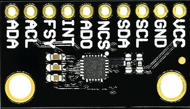
Pin Configuration and Descriptions

The ICM-20948 is typically available in a 24-pin QFN package. Below is the pin configuration:

Pin Number Pin Name Description
1 VDD Power supply input (1.71V to 3.6V)
2 GND Ground connection
3 SCL/SCLK I²C clock line / SPI clock
4 SDA/SDI I²C data line / SPI data input
5 AD0/SDO I²C address select / SPI data output
6 INT Interrupt output
7 FSYNC Frame synchronization input/output
8-24 NC No connection (reserved for future use)

Usage Instructions

The ICM-20948 can be used in a variety of circuits and is compatible with microcontrollers such as the Arduino UNO. Below are the steps to use the ICM-20948 in a circuit:

Connecting the ICM-20948 to an Arduino UNO

  1. Power Supply: Connect the VDD pin of the ICM-20948 to the 3.3V pin of the Arduino UNO. Connect the GND pin to the Arduino's GND.
  2. I²C Communication:
    • Connect the SCL pin of the ICM-20948 to the A5 pin of the Arduino UNO.
    • Connect the SDA pin of the ICM-20948 to the A4 pin of the Arduino UNO.
  3. Address Selection: Connect the AD0 pin to GND for the default I²C address (0x68). Connect it to VDD for the alternate address (0x69).
  4. Interrupt Pin (Optional): Connect the INT pin to a digital input pin on the Arduino if you want to use interrupts.

Sample Arduino Code

Below is an example Arduino sketch to read data from the ICM-20948 using the I²C interface:

#include <Wire.h>

// ICM-20948 I2C address (default is 0x68 if AD0 is connected to GND)
#define ICM20948_ADDRESS 0x68

// Register addresses
#define WHO_AM_I 0x00
#define ACCEL_XOUT_H 0x2D

void setup() {
  Wire.begin(); // Initialize I2C communication
  Serial.begin(9600); // Initialize serial communication for debugging

  // Check if the ICM-20948 is connected
  Wire.beginTransmission(ICM20948_ADDRESS);
  Wire.write(WHO_AM_I); // Request the WHO_AM_I register
  Wire.endTransmission();
  Wire.requestFrom(ICM20948_ADDRESS, 1);

  if (Wire.available()) {
    byte whoAmI = Wire.read();
    if (whoAmI == 0xEA) { // Expected WHO_AM_I response for ICM-20948
      Serial.println("ICM-20948 detected!");
    } else {
      Serial.println("ICM-20948 not detected. Check connections.");
    }
  }
}

void loop() {
  // Read accelerometer data
  Wire.beginTransmission(ICM20948_ADDRESS);
  Wire.write(ACCEL_XOUT_H); // Request accelerometer X-axis high byte
  Wire.endTransmission();
  Wire.requestFrom(ICM20948_ADDRESS, 6); // Request 6 bytes (X, Y, Z)

  if (Wire.available() == 6) {
    int16_t accelX = (Wire.read() << 8) | Wire.read();
    int16_t accelY = (Wire.read() << 8) | Wire.read();
    int16_t accelZ = (Wire.read() << 8) | Wire.read();

    Serial.print("Accel X: ");
    Serial.print(accelX);
    Serial.print(" Y: ");
    Serial.print(accelY);
    Serial.print(" Z: ");
    Serial.println(accelZ);
  }

  delay(500); // Wait 500ms before the next reading
}

Important Considerations

  • Ensure the ICM-20948 is powered with a voltage within its operating range (1.71V to 3.6V).
  • Use appropriate pull-up resistors (typically 4.7kΩ) on the I²C lines (SCL and SDA) if they are not already present on your breakout board.
  • Avoid excessive noise on the power supply and communication lines to ensure accurate readings.

Troubleshooting and FAQs

Common Issues

  1. ICM-20948 Not Detected

    • Cause: Incorrect wiring or I²C address mismatch.
    • Solution: Verify the connections and ensure the AD0 pin is set correctly for the desired I²C address.
  2. Inaccurate Sensor Readings

    • Cause: Calibration not performed or excessive noise in the environment.
    • Solution: Perform sensor calibration and ensure the sensor is mounted securely to minimize vibrations.
  3. No Data from the Sensor

    • Cause: Incorrect register address or communication failure.
    • Solution: Double-check the register addresses in your code and ensure proper pull-up resistors are used on the I²C lines.

FAQs

Q: Can the ICM-20948 be used with SPI instead of I²C?
A: Yes, the ICM-20948 supports both I²C and SPI communication. For SPI, connect the SCL/SCLK, SDA/SDI, and AD0/SDO pins to the appropriate SPI pins on your microcontroller.

Q: How do I calibrate the ICM-20948?
A: Calibration involves collecting raw data from the gyroscope, accelerometer, and magnetometer, and applying offsets to account for biases. Many libraries provide built-in calibration functions.

Q: What is the maximum sampling rate of the ICM-20948?
A: The ICM-20948 supports a maximum sampling rate of 1125 Hz for the gyroscope and accelerometer.

By following this documentation, you can effectively integrate the ICM-20948 into your projects for precise motion and orientation tracking.