How to Use CJMCU-1051: Examples, Pinouts, and Specs
Introduction
The CJMCU-1051 is a high-precision digital-to-analog converter (DAC) designed to convert digital signals into analog voltages with exceptional accuracy. Manufactured by CJMCU, this component is widely used in applications requiring precise analog signal generation, such as audio systems, waveform generation, and industrial control systems. Its compact design, low power consumption, and high resolution make it an ideal choice for embedded systems and portable devices.
Explore Projects Built with CJMCU-1051
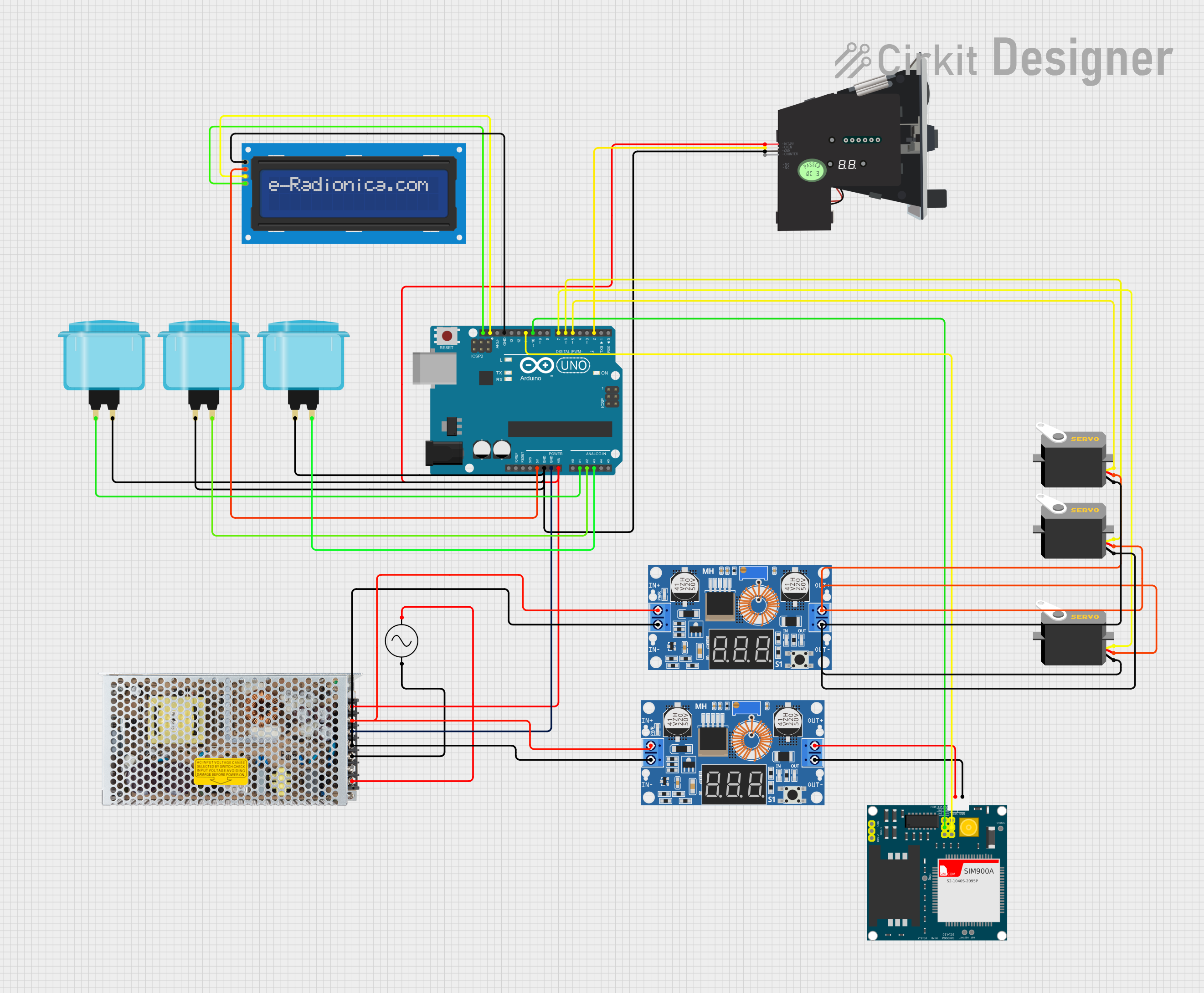


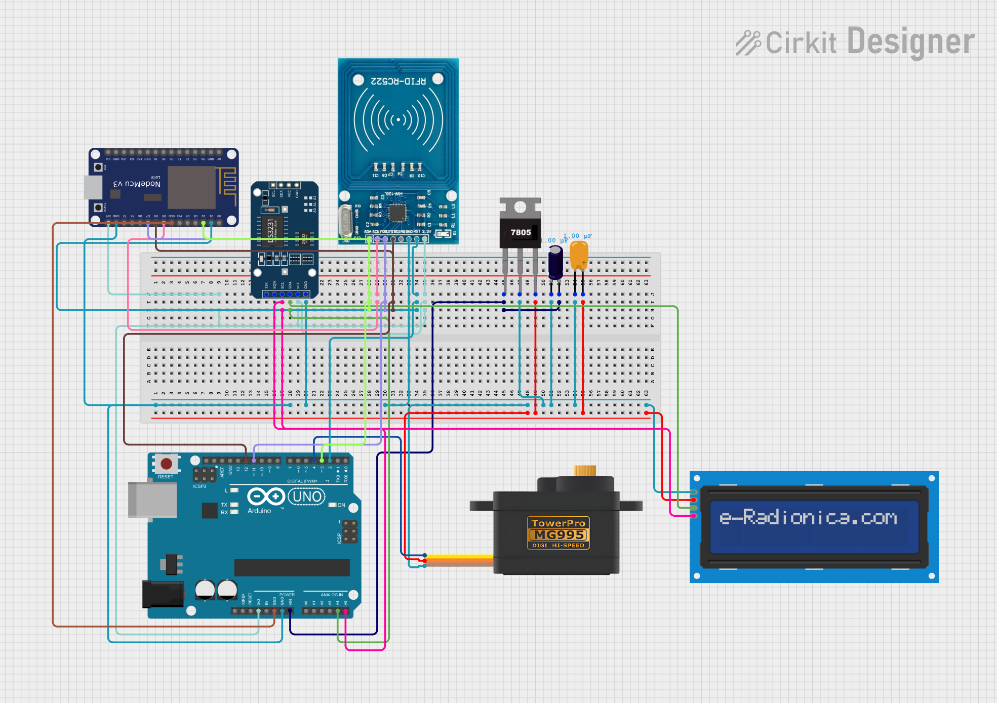
Explore Projects Built with CJMCU-1051
Common Applications:
- Audio signal processing and playback
- Waveform generation for testing and measurement
- Industrial control systems
- Analog control in robotics and automation
- Precision voltage generation for calibration systems
Technical Specifications
The following table outlines the key technical details of the CJMCU-1051:
| Parameter | Value |
|---|---|
| Manufacturer | CJMCU |
| Part Number | CJMCU-1051 |
| Resolution | 12-bit |
| Output Voltage Range | 0V to 3.3V (or 0V to 5V, depending on VCC) |
| Supply Voltage (VCC) | 2.7V to 5.5V |
| Interface | I2C |
| Power Consumption | Low power (typical < 1mW) |
| Operating Temperature | -40°C to +85°C |
| Package Type | SOP-8 |
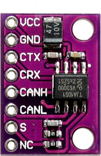
Pin Configuration and Descriptions
The CJMCU-1051 features an 8-pin configuration. The table below describes each pin:
| Pin Number | Pin Name | Description |
|---|---|---|
| 1 | VCC | Power supply input (2.7V to 5.5V) |
| 2 | GND | Ground connection |
| 3 | SDA | I2C data line |
| 4 | SCL | I2C clock line |
| 5 | A0 | I2C address selection bit |
| 6 | A1 | I2C address selection bit |
| 7 | VOUT | Analog voltage output |
| 8 | NC | No connection (leave unconnected) |
Usage Instructions
Connecting the CJMCU-1051 in a Circuit
- Power Supply: Connect the VCC pin to a 3.3V or 5V power source, depending on your system's requirements. Connect the GND pin to the ground of your circuit.
- I2C Interface: Connect the SDA and SCL pins to the corresponding I2C data and clock lines of your microcontroller. Use pull-up resistors (typically 4.7kΩ) on these lines if not already present.
- Address Selection: Use the A0 and A1 pins to configure the I2C address of the device. These pins can be connected to VCC or GND to set the address.
- Output Voltage: The VOUT pin provides the analog voltage output. Connect this pin to the desired load or circuit.
Important Considerations
- Ensure the supply voltage (VCC) matches the logic level of your microcontroller to avoid communication issues.
- Use decoupling capacitors (e.g., 0.1µF) near the VCC pin to reduce noise and improve stability.
- Avoid exceeding the maximum output current rating of the VOUT pin to prevent damage.
Example: Using CJMCU-1051 with Arduino UNO
Below is an example of how to interface the CJMCU-1051 with an Arduino UNO to generate an analog voltage:
#include <Wire.h> // Include the Wire library for I2C communication

#define DAC_I2C_ADDRESS 0x60 // Default I2C address of CJMCU-1051

void setup() {
  Wire.begin(); // Initialize I2C communication
  Serial.begin(9600); // Initialize serial communication for debugging
}

void loop() {
  uint16_t digitalValue = 2048; // Example 12-bit value (midpoint for 0-4095 range)

  // Send the digital value to the DAC
  Wire.beginTransmission(DAC_I2C_ADDRESS);
  Wire.write((digitalValue >> 8) & 0xFF); // Send the upper 8 bits
  Wire.write(digitalValue & 0xFF);        // Send the lower 8 bits
  Wire.endTransmission();

  Serial.println("Analog voltage updated!"); // Debug message
  delay(1000); // Wait for 1 second before updating again
}
Notes:
- The
digitalValuevariable represents the 12-bit digital input to the DAC. Adjust this value to generate different analog voltages. - The output voltage is proportional to the digital value:
[ V_{OUT} = \frac{DigitalValue}{4095} \times V_{REF} ]
where ( V_{REF} ) is the reference voltage (typically equal to VCC).
Troubleshooting and FAQs
Common Issues and Solutions
No Output Voltage on VOUT Pin:
- Verify that the power supply (VCC) and ground (GND) are properly connected.
- Check the I2C connections (SDA and SCL) and ensure pull-up resistors are present.
- Confirm that the I2C address matches the configuration of the A0 and A1 pins.
Incorrect Output Voltage:
- Ensure the digital value sent to the DAC is within the valid range (0 to 4095 for 12-bit resolution).
- Verify that the reference voltage (VCC) is stable and noise-free.
I2C Communication Failure:
- Check the wiring and ensure the SDA and SCL lines are not swapped.
- Confirm that the microcontroller and DAC are operating at compatible voltage levels.
- Use a logic analyzer or oscilloscope to debug the I2C signals.
FAQs
Q: Can the CJMCU-1051 operate at 3.3V?
A: Yes, the CJMCU-1051 supports a supply voltage range of 2.7V to 5.5V, making it compatible with both 3.3V and 5V systems.
Q: What is the maximum output current of the VOUT pin?
A: The VOUT pin is designed for low-current applications. For higher current requirements, use a buffer or amplifier circuit.
Q: How do I set the I2C address?
A: The I2C address is configured using the A0 and A1 pins. Connect these pins to VCC or GND to select the desired address.
Q: Can I use the CJMCU-1051 for audio applications?
A: Yes, the high resolution and low noise of the CJMCU-1051 make it suitable for audio signal generation and processing.
By following this documentation, you can effectively integrate the CJMCU-1051 into your projects and achieve precise digital-to-analog conversion.