
How to Use Stepper Motor Driver Controller PWM: Examples, Pinouts, and Specs
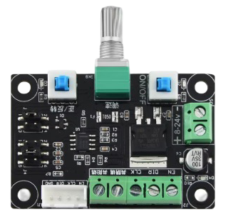
 Design with Stepper Motor Driver Controller PWM in Cirkit Designer
Introduction
The Stepper Motor Driver Controller PWM is an electronic module designed to control stepper motors using Pulse Width Modulation (PWM) signals. It provides precise control over the speed, direction, and position of stepper motors, making it ideal for applications requiring accurate motion control. This component is widely used in robotics, 3D printers, CNC machines, and other automation systems.
By converting low-power control signals into high-power outputs, the driver ensures efficient operation of stepper motors while protecting them from overcurrent and overheating.
Explore Projects Built with Stepper Motor Driver Controller PWM
 Open Project in Cirkit Designer
 Open Project in Cirkit Designer
 Open Project in Cirkit Designer
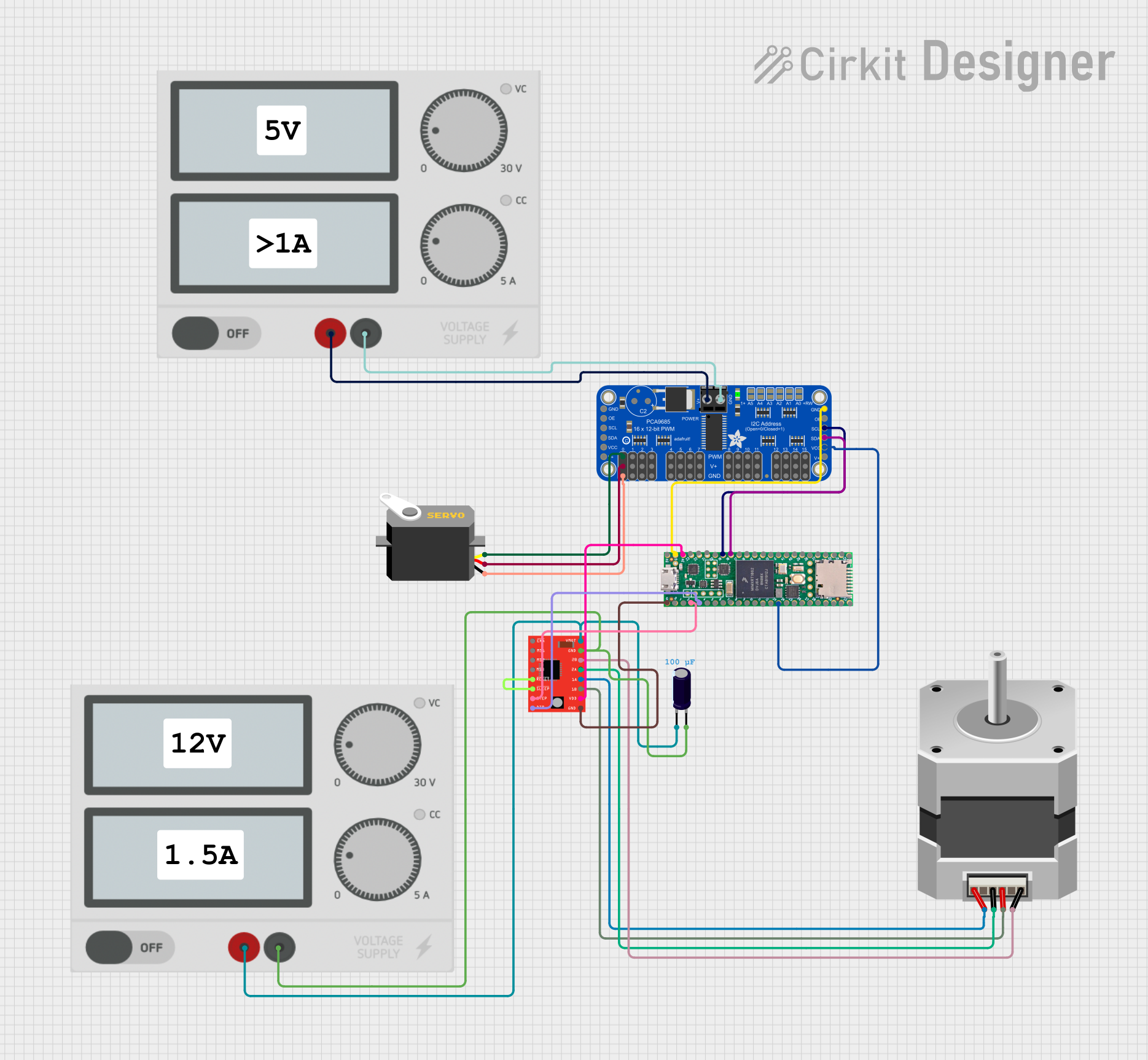 Open Project in Cirkit Designer
Explore Projects Built with Stepper Motor Driver Controller PWM
Open Project in Cirkit DesignerOpen Project in Cirkit DesignerOpen Project in Cirkit DesignerOpen Project in Cirkit DesignerTechnical Specifications
Below are the key technical details of the Stepper Motor Driver Controller PWM:
General Specifications
- Input Voltage Range: 8V to 35V DC
- Output Current: Up to 2A per phase
- Control Signal Voltage: 3.3V or 5V logic compatible
- Microstepping Modes: Full step, half step, 1/4 step, 1/8 step, 1/16 step
- PWM Frequency: Up to 20 kHz
- Built-in Protections: Overcurrent, thermal shutdown, and undervoltage lockout
Pin Configuration and Descriptions
The pinout of the Stepper Motor Driver Controller PWM is as follows:
| Pin Name | Type | Description |
|---|---|---|
| VCC | Power Input | Connect to the power supply (8V to 35V DC). |
| GND | Ground | Connect to the ground of the power supply and control circuit. |
| STEP | Input Signal | Receives the step signal to control motor steps. |
| DIR | Input Signal | Determines the direction of motor rotation (HIGH for one direction, LOW for the other). |
| EN | Input Signal | Enable pin to activate or deactivate the motor driver (LOW to enable, HIGH to disable). |
| MS1, MS2, MS3 | Input Signal | Microstepping mode selection pins. |
| A+, A- | Motor Output | Connect to one coil of the stepper motor. |
| B+, B- | Motor Output | Connect to the other coil of the stepper motor. |
Usage Instructions
How to Use the Component in a Circuit
- Power Supply: Connect the VCC and GND pins to a DC power supply within the specified voltage range.
- Motor Connection: Attach the stepper motor coils to the A+, A-, B+, and B- pins. Ensure proper wiring to avoid motor malfunction.
- Control Signals:
- Connect the STEP and DIR pins to a microcontroller or other control circuit.
- Use the EN pin to enable or disable the driver as needed.
- Microstepping Configuration: Set the MS1, MS2, and MS3 pins to HIGH or LOW to select the desired microstepping mode:
- Full Step: MS1 = LOW, MS2 = LOW, MS3 = LOW
- Half Step: MS1 = HIGH, MS2 = LOW, MS3 = LOW
- 1/4 Step: MS1 = LOW, MS2 = HIGH, MS3 = LOW
- 1/8 Step: MS1 = HIGH, MS2 = HIGH, MS3 = LOW
- 1/16 Step: MS1 = HIGH, MS2 = HIGH, MS3 = HIGH
Important Considerations and Best Practices
- Ensure the power supply voltage matches the motor's requirements to avoid damage.
- Use decoupling capacitors near the VCC and GND pins to reduce noise and improve stability.
- Avoid exceeding the maximum current rating to prevent overheating or damage to the driver.
- Use proper heat dissipation methods, such as heatsinks, if the driver operates at high currents for extended periods.
Example Code for Arduino UNO
Below is an example code to control a stepper motor using the Stepper Motor Driver Controller PWM with an Arduino UNO:
// Define pin connections
#define STEP_PIN 3  // Pin connected to STEP input of the driver
#define DIR_PIN 4   // Pin connected to DIR input of the driver
#define EN_PIN 5    // Pin connected to EN input of the driver

void setup() {
  // Set pin modes
  pinMode(STEP_PIN, OUTPUT);
  pinMode(DIR_PIN, OUTPUT);
  pinMode(EN_PIN, OUTPUT);

  // Enable the driver
  digitalWrite(EN_PIN, LOW);  // LOW enables the driver
}

void loop() {
  // Set direction
  digitalWrite(DIR_PIN, HIGH);  // HIGH for one direction, LOW for the other

  // Generate step pulses
  for (int i = 0; i < 200; i++) {  // 200 steps for one revolution (example)
    digitalWrite(STEP_PIN, HIGH);  // Set STEP pin HIGH
    delayMicroseconds(1000);       // Wait 1 ms (adjust for speed control)
    digitalWrite(STEP_PIN, LOW);   // Set STEP pin LOW
    delayMicroseconds(1000);       // Wait 1 ms
  }

  delay(1000);  // Wait 1 second before changing direction
  digitalWrite(DIR_PIN, LOW);  // Change direction
}
Troubleshooting and FAQs
Common Issues and Solutions
Motor Not Moving:
- Ensure the power supply is connected and within the specified voltage range.
- Verify the STEP and DIR signals are being sent correctly from the microcontroller.
- Check motor wiring for loose or incorrect connections.
Overheating Driver:
- Reduce the current limit if adjustable on the driver.
- Use a heatsink or active cooling to dissipate heat.
Erratic Motor Movement:
- Check for noise in the control signals and use proper grounding.
- Verify the microstepping mode configuration (MS1, MS2, MS3 pins).
Driver Not Enabling:
- Ensure the EN pin is set to LOW to enable the driver.
- Check for proper connections and continuity in the circuit.
FAQs
Can I use a 12V stepper motor with this driver? Yes, as long as the power supply voltage is within the 8V to 35V range and the motor's current rating does not exceed 2A per phase.
What happens if I exceed the current limit? The driver has built-in overcurrent protection, but exceeding the limit repeatedly may cause thermal shutdown or permanent damage.
How do I adjust the speed of the motor? Adjust the delay between STEP pulses in your code. Shorter delays result in higher speeds, while longer delays reduce speed.
This documentation provides a comprehensive guide to using the Stepper Motor Driver Controller PWM effectively. Follow the instructions and best practices to ensure reliable operation in your projects.