How to Use Emergency STOP: Examples, Pinouts, and Specs
Introduction
The Emergency STOP (E-STOP) is a safety device designed to immediately halt the operation of machinery or equipment in case of an emergency. It ensures a quick response to prevent accidents, protect personnel, and safeguard equipment. E-STOPs are commonly used in industrial environments, manufacturing plants, and any application where machinery poses a potential safety risk.
Explore Projects Built with Emergency STOP


Explore Projects Built with Emergency STOP
Common Applications and Use Cases
- Industrial machinery and conveyor systems
- Robotics and automated systems
- CNC machines and heavy equipment
- Elevators and escalators
- Laboratory and testing equipment
- Any environment requiring immediate shutdown for safety
Technical Specifications
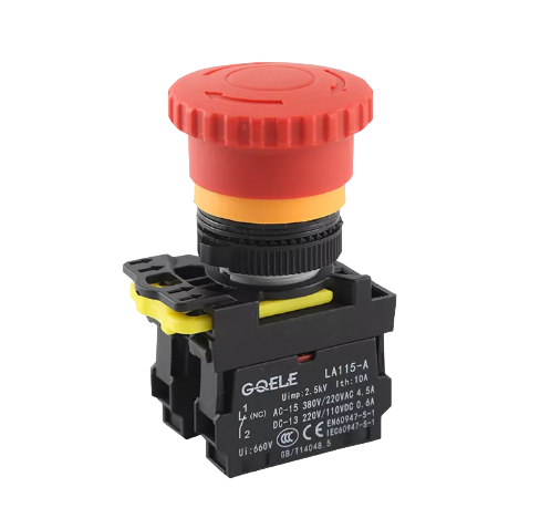
The Emergency STOP button is typically a momentary, normally closed (NC) switch with a latching mechanism. Below are the general technical specifications:
| Parameter | Value |
|---|---|
| Operating Voltage | 12V to 240V AC/DC (varies by model) |
| Current Rating | 1A to 10A (varies by model) |
| Contact Configuration | Normally Closed (NC) or NC + NO |
| Actuation Force | 10-50N (varies by model) |
| Reset Mechanism | Twist or pull-to-release |
| Mounting Hole Diameter | 16mm, 22mm, or 30mm |
| Operating Temperature | -25°C to +70°C |
| IP Rating | IP65 or higher (dust and water resistance) |
Pin Configuration and Descriptions
The Emergency STOP button typically has two or more terminals for wiring. Below is a table describing the pin configuration:
| Pin Name | Description |
|---|---|
| NC (Normally Closed) | Connects to the circuit; opens when the button is pressed, breaking the circuit. |
| NO (Normally Open) | Optional; closes when the button is pressed, used for signaling or alarms. |
| COM (Common) | Common terminal for NC and NO connections. |
Usage Instructions
How to Use the Emergency STOP in a Circuit
Wiring the E-STOP Button:
- Connect the NC terminal in series with the power supply line of the machinery or equipment.
- Optionally, connect the NO terminal to an alarm or indicator circuit to signal when the E-STOP is activated.
- Ensure proper insulation and secure connections to avoid accidental disconnections.
Mounting the E-STOP:
- Drill a hole in the control panel or mounting surface matching the button's diameter (e.g., 22mm).
- Insert the E-STOP button and secure it using the provided locking nut.
Resetting the E-STOP:
- After activation, twist or pull the button (depending on the model) to reset it and restore the circuit.
Important Considerations and Best Practices
- Always verify the voltage and current ratings of the E-STOP button to ensure compatibility with your system.
- Test the E-STOP functionality regularly to ensure it operates correctly.
- Use an E-STOP button with an appropriate IP rating for environments exposed to dust, water, or other contaminants.
- Label the E-STOP button clearly to ensure it is easily identifiable in an emergency.
- For systems controlled by microcontrollers (e.g., Arduino), use the E-STOP to cut power to the entire system rather than relying solely on software-based safety mechanisms.
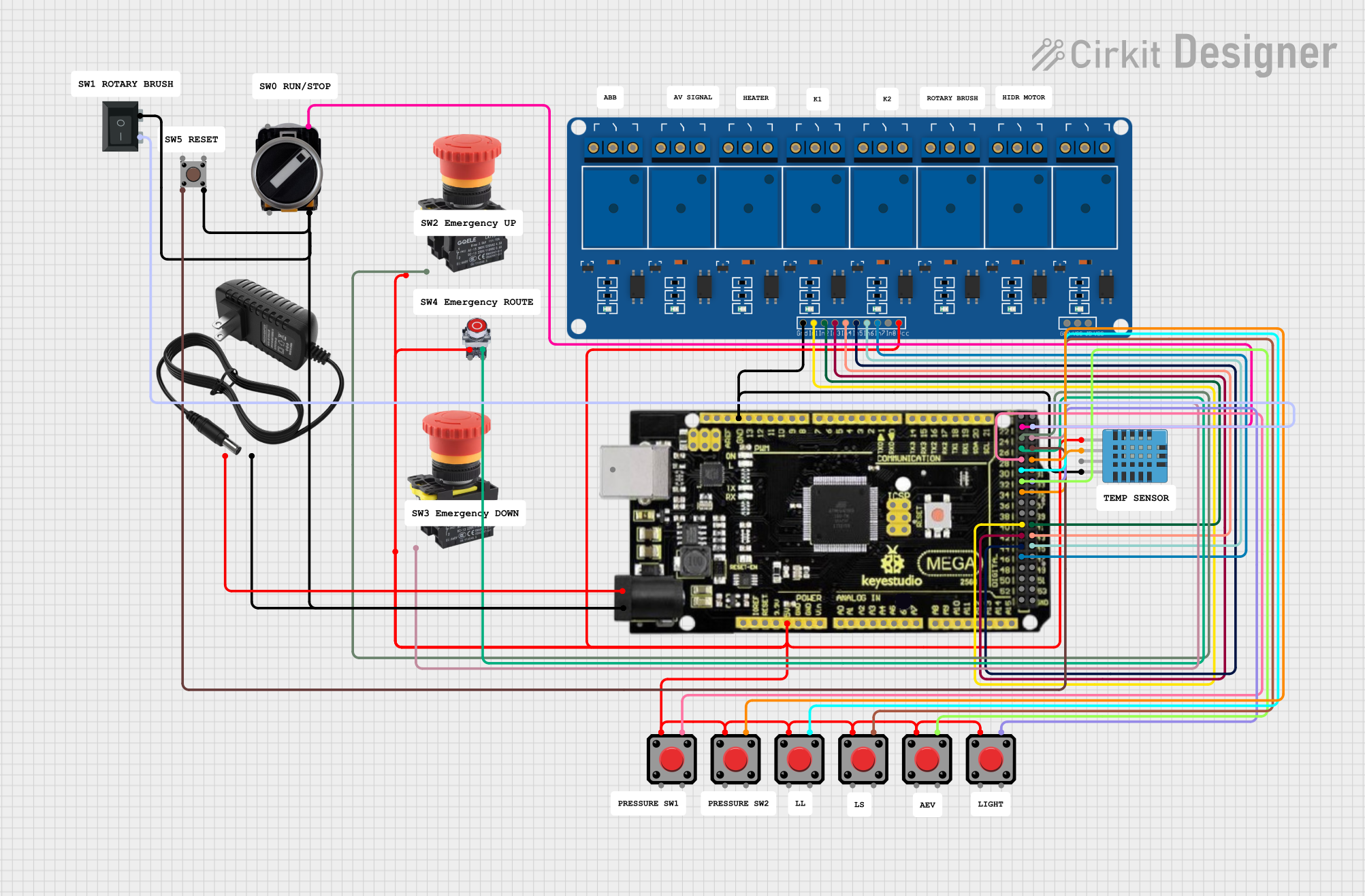
Example: Connecting an E-STOP to an Arduino UNO
Below is an example of how to use an E-STOP button with an Arduino UNO to monitor its state and trigger an emergency response:
// Define the pin connected to the NC terminal of the E-STOP button
const int eStopPin = 2; // Digital pin 2

// Define the pin for an LED to indicate emergency state
const int ledPin = 13; // Built-in LED on most Arduino boards

void setup() {
  pinMode(eStopPin, INPUT_PULLUP); // Use internal pull-up resistor
  pinMode(ledPin, OUTPUT);         // Set LED pin as output
  digitalWrite(ledPin, LOW);       // Ensure LED is off initially
  Serial.begin(9600);              // Initialize serial communication
}

void loop() {
  // Read the state of the E-STOP button
  int eStopState = digitalRead(eStopPin);

  if (eStopState == HIGH) {
    // E-STOP is not pressed (circuit closed)
    digitalWrite(ledPin, LOW);    // Turn off LED
    Serial.println("System running normally.");
  } else {
    // E-STOP is pressed (circuit open)
    digitalWrite(ledPin, HIGH);   // Turn on LED
    Serial.println("EMERGENCY STOP ACTIVATED!");
    // Add additional emergency handling code here
  }

  delay(100); // Small delay for stability
}
Note: The NC terminal is connected to the Arduino pin with a pull-up resistor. When the E-STOP is pressed, the circuit opens, and the Arduino detects a LOW signal.
Troubleshooting and FAQs
Common Issues and Solutions
E-STOP Button Does Not Stop the Machinery:
- Cause: Incorrect wiring or loose connections.
- Solution: Verify the wiring, ensuring the NC terminal is properly connected in series with the power supply line.
E-STOP Button Does Not Reset:
- Cause: Faulty reset mechanism or debris in the button.
- Solution: Inspect the button for physical damage or obstructions. Replace if necessary.
False Triggers or Unintended Activation:
- Cause: Electrical noise or vibration.
- Solution: Use shielded cables and secure the button to minimize vibration.
Arduino Does Not Detect E-STOP Activation:
- Cause: Incorrect pin configuration or missing pull-up resistor.
- Solution: Ensure the pin is configured as
INPUT_PULLUPin the Arduino code.
FAQs
Q1: Can I use an E-STOP button with high-power equipment?
A1: Yes, but ensure the button's voltage and current ratings match or exceed the equipment's requirements. For very high-power systems, use the E-STOP to control a relay or contactor.
Q2: How often should I test the E-STOP button?
A2: Regular testing is recommended, typically during routine maintenance or at least once a month.
Q3: Can I use an E-STOP button outdoors?
A3: Yes, but ensure the button has an appropriate IP rating (e.g., IP65 or higher) for outdoor use.
Q4: What happens if the E-STOP button fails?
A4: Most E-STOP buttons are designed to fail-safe, meaning they will open the circuit in case of a failure. However, regular testing is essential to ensure reliability.