How to Use SI-TEX G1 Satellite Compass: Examples, Pinouts, and Specs
Introduction
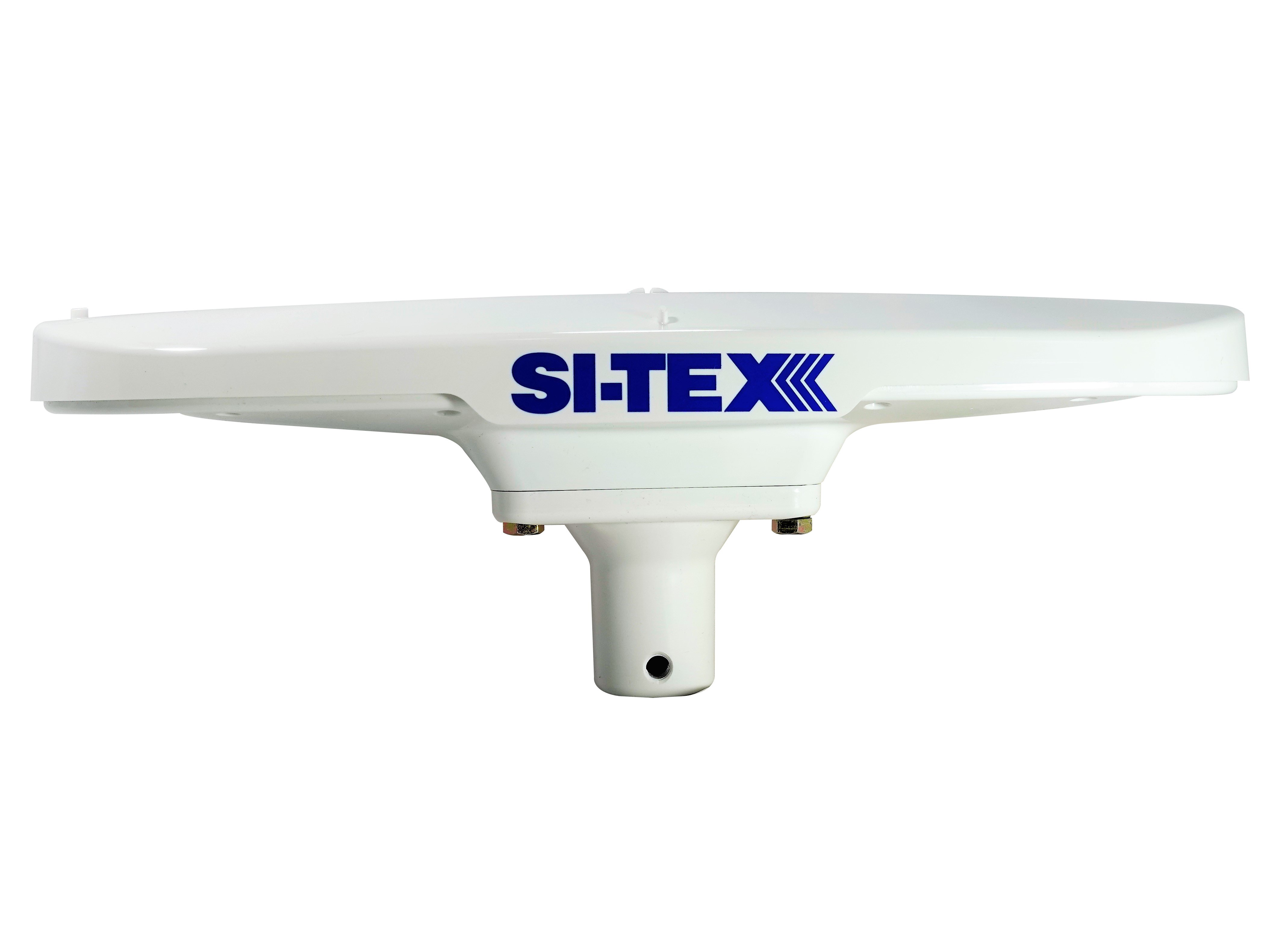
The SI-TEX G1 Satellite Compass is a state-of-the-art marine navigation device designed to provide highly accurate heading information. Utilizing advanced satellite signal processing, the G1 compass offers exceptional reliability and precision for marine vessels such as boats, yachts, and ships. This device is an essential tool for mariners seeking to improve their navigation capabilities and autopilot system performance, thereby enhancing overall safety and efficiency during maritime operations.
Explore Projects Built with SI-TEX G1 Satellite Compass


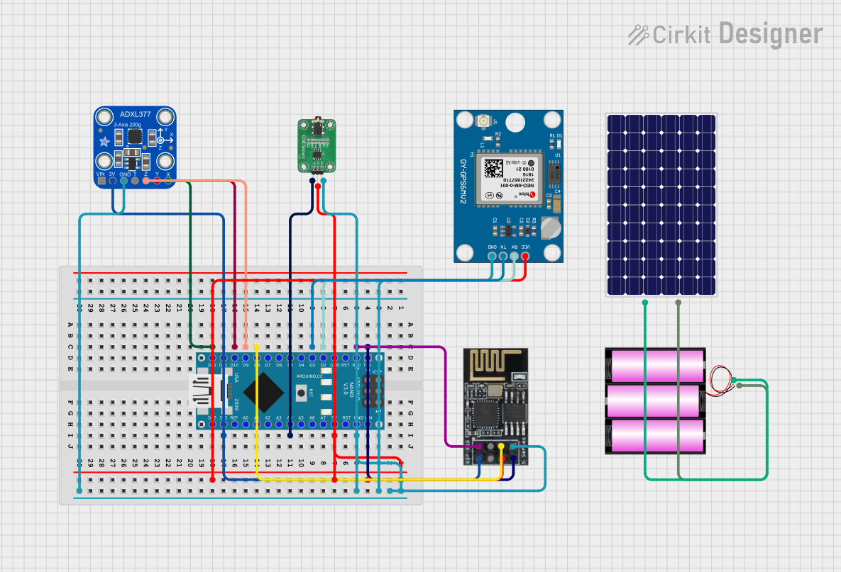
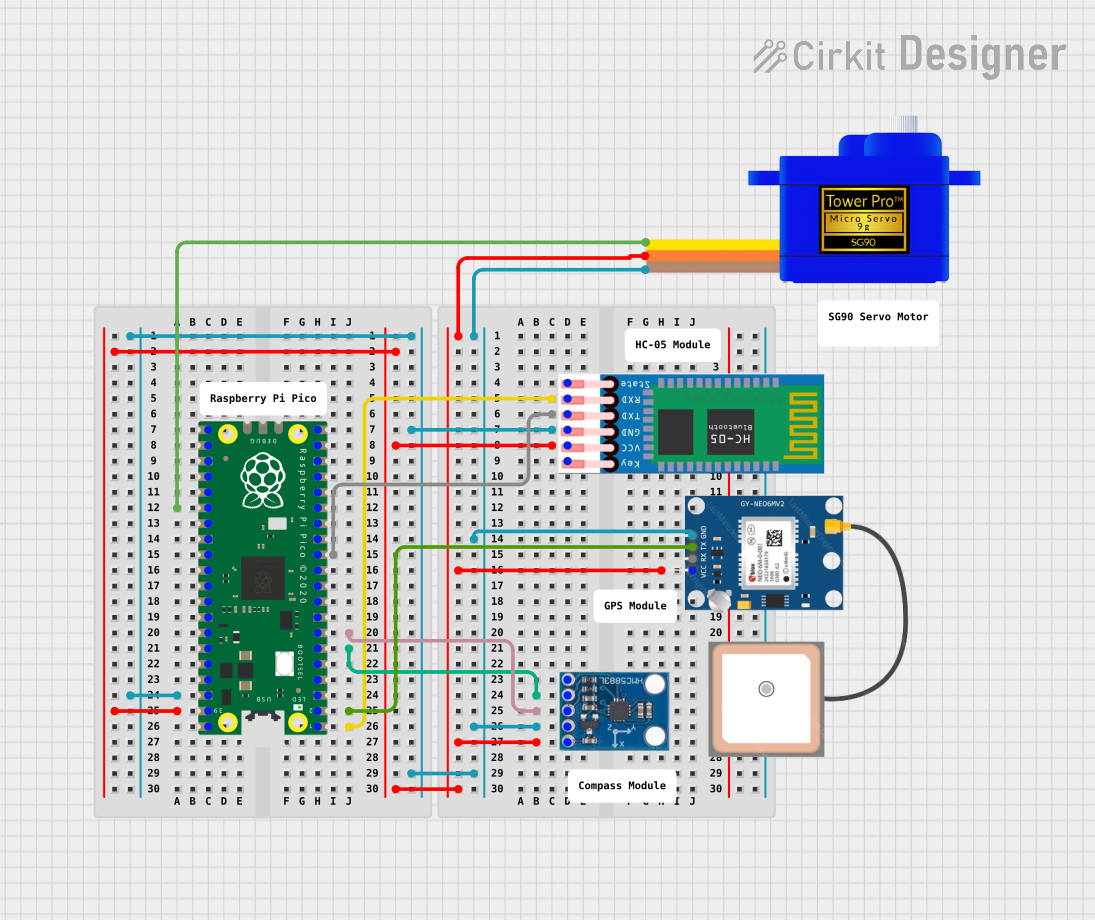
Explore Projects Built with SI-TEX G1 Satellite Compass
Common Applications and Use Cases
- Marine navigation for boats, yachts, and ships
- Integration with autopilot systems
- Real-time heading display for precise course adjustments
- Use in conjunction with chartplotters and radar systems
Technical Specifications
Key Technical Details
- Accuracy: +/- 0.5 degrees RMS (Heading)
- Satellite Tracking: Multi-GNSS Support (GPS, GLONASS, Galileo, BeiDou)
- Update Rate: 10 Hz
- Operating Voltage: 9 to 36 VDC
- Power Consumption: Less than 3W
- Operating Temperature: -25°C to +70°C
- Waterproof Rating: IPX6 and IPX7
Pin Configuration and Descriptions
| Pin Number | Description | Voltage/Signal Type |
|---|---|---|
| 1 | Power Supply (+) | 9-36 VDC |
| 2 | Power Supply (-) | Ground |
| 3 | NMEA 0183 TX (+) | Data Output |
| 4 | NMEA 0183 RX (+) | Data Input |
| 5 | NMEA 0183 Common (-) | Signal Ground |
| 6 | CAN High | Data CAN High |
| 7 | CAN Low | Data CAN Low |
| 8 | Shield | Protective Ground |
Usage Instructions
How to Use the Component in a Circuit
- Power Connection: Connect the power supply to pins 1 (+) and 2 (-) ensuring the voltage is within the specified range (9-36 VDC).
- Data Communication: Connect the NMEA 0183 TX and RX lines to your marine equipment for data transmission and reception. Ensure proper grounding by connecting pin 5 to the signal ground of your equipment.
- CAN Bus Integration: If your system supports CAN bus, connect the CAN High and CAN Low to the respective CAN bus lines of your navigation system.
- Shielding: Connect the shield (pin 8) to the protective ground in your system to minimize electromagnetic interference.
Important Considerations and Best Practices
- Ensure all connections are secure and watertight to prevent damage from the marine environment.
- Avoid placing the compass near magnetic or metallic objects that could interfere with its accuracy.
- Regularly calibrate the compass according to the manufacturer's instructions to maintain optimal performance.
- Update the firmware as recommended to benefit from the latest improvements and features.
Troubleshooting and FAQs
Common Issues
- Inaccurate Heading Information: Ensure the compass is properly calibrated and not obstructed by metallic objects.
- No Power: Check the power supply connections and voltage levels.
- Intermittent Data Output: Verify the integrity of the NMEA 0183 or CAN bus connections.
Solutions and Tips for Troubleshooting
- Calibration: Perform a calibration routine as outlined in the manufacturer's manual.
- Connection Check: Inspect all connections for corrosion or damage, and ensure they are secure.
- Voltage Testing: Use a multimeter to confirm the power supply is within the specified range.
FAQs
Q: Can the SI-TEX G1 Satellite Compass be used with any marine navigation system? A: The compass is designed to be compatible with systems that accept NMEA 0183 or CAN bus data inputs.
Q: How often should the compass be calibrated? A: Calibration frequency can vary based on usage and environmental factors. Refer to the manufacturer's guidelines for specific recommendations.
Q: What should I do if the compass is not powering on? A: Verify the power supply connections and ensure the voltage is within the specified range. Check for any blown fuses or circuit breakers.
Note: This documentation is provided for informational purposes only and may not cover all aspects of the SI-TEX G1 Satellite Compass operation. For comprehensive instructions and support, refer to the official manufacturer's manual and technical support resources.