Cirkit Designer Logo
Cirkit Designer
Your all-in-one circuit design IDE
Home / 
Component Documentation

How to Use Matrix Portal S3: Examples, Pinouts, and Specs

Image of Matrix Portal S3
Cirkit Designer LogoDesign with Matrix Portal S3 in Cirkit Designer

Introduction

The Matrix Portal S3 is a powerful microcontroller board specifically designed for driving RGB LED matrices. It features built-in Wi-Fi connectivity and is fully compatible with CircuitPython, making it an excellent choice for creating interactive displays, IoT-enabled signage, and other LED matrix-based projects. Its ease of programming and integration allows both beginners and advanced users to quickly bring their ideas to life.

Explore Projects Built with Matrix Portal S3

Use Cirkit Designer to design, explore, and prototype these projects online. Some projects support real-time simulation. Click "Open Project" to start designing instantly!
Battery-Powered UPS System with Waveshare UPS 3S and Solar Charger
Image of Copy of s: A project utilizing Matrix Portal S3 in a practical application
This circuit is a power management system that integrates a 12V power supply, a solar charger power bank, and multiple Li-ion batteries to provide a stable power output. The Waveshare UPS 3S manages the input from the power sources and batteries, ensuring continuous power delivery. The MRB045 module is used to interface the solar charger with the rest of the system.
Cirkit Designer LogoOpen Project in Cirkit Designer
NFC-Enabled Access Control System with Time Logging
Image of doorlock: A project utilizing Matrix Portal S3 in a practical application
This circuit is designed for access control with time tracking capabilities. It features an NFC/RFID reader for authentication, an RTC module (DS3231) for real-time clock functionality, and an OLED display for user interaction. A 12V relay controls a magnetic lock, which is activated upon successful NFC/RFID authentication, and a button switch is likely used for manual operation or input. The T8_S3 microcontroller serves as the central processing unit, interfacing with the NFC/RFID reader, RTC, OLED, and relay to manage the access control logic.
Cirkit Designer LogoOpen Project in Cirkit Designer
ESP32-Based Smart Irrigation and Environmental Monitoring System
Image of Skripsi: A project utilizing Matrix Portal S3 in a practical application
This is an automated environmental control system for plant growth that uses an ESP32 to monitor soil moisture and pH levels, and to manage irrigation through solenoid valves. The system aims to maintain optimal growing conditions by adjusting watering schedules based on sensor inputs.
Cirkit Designer LogoOpen Project in Cirkit Designer
Solar-Powered Automated Irrigation System with Soil Moisture Sensing and TFT Display Interface
Image of SSPIS: A project utilizing Matrix Portal S3 in a practical application
This circuit is designed to be a solar-powered irrigation system with moisture sensing capabilities. It uses a solar panel connected to a charge controller to charge a battery, which powers the system. The ESP32-S3 microcontroller reads data from capacitive soil moisture sensors and controls solenoid valves via a 3-channel relay to regulate water flow based on the moisture levels. Additionally, the system includes a DHT22 sensor for temperature and humidity readings, a voltage regulator to step down voltage for the microcontroller and sensors, and an ili9341 TFT display for user interface, which is also interfaced with the ESP32-S3. User inputs are managed through arcade buttons connected to the microcontroller.
Cirkit Designer LogoOpen Project in Cirkit Designer

Explore Projects Built with Matrix Portal S3

Use Cirkit Designer to design, explore, and prototype these projects online. Some projects support real-time simulation. Click "Open Project" to start designing instantly!
Image of Copy of s: A project utilizing Matrix Portal S3 in a practical application
Battery-Powered UPS System with Waveshare UPS 3S and Solar Charger
This circuit is a power management system that integrates a 12V power supply, a solar charger power bank, and multiple Li-ion batteries to provide a stable power output. The Waveshare UPS 3S manages the input from the power sources and batteries, ensuring continuous power delivery. The MRB045 module is used to interface the solar charger with the rest of the system.
Cirkit Designer LogoOpen Project in Cirkit Designer
Image of doorlock: A project utilizing Matrix Portal S3 in a practical application
NFC-Enabled Access Control System with Time Logging
This circuit is designed for access control with time tracking capabilities. It features an NFC/RFID reader for authentication, an RTC module (DS3231) for real-time clock functionality, and an OLED display for user interaction. A 12V relay controls a magnetic lock, which is activated upon successful NFC/RFID authentication, and a button switch is likely used for manual operation or input. The T8_S3 microcontroller serves as the central processing unit, interfacing with the NFC/RFID reader, RTC, OLED, and relay to manage the access control logic.
Cirkit Designer LogoOpen Project in Cirkit Designer
Image of Skripsi: A project utilizing Matrix Portal S3 in a practical application
ESP32-Based Smart Irrigation and Environmental Monitoring System
This is an automated environmental control system for plant growth that uses an ESP32 to monitor soil moisture and pH levels, and to manage irrigation through solenoid valves. The system aims to maintain optimal growing conditions by adjusting watering schedules based on sensor inputs.
Cirkit Designer LogoOpen Project in Cirkit Designer
Image of SSPIS: A project utilizing Matrix Portal S3 in a practical application
Solar-Powered Automated Irrigation System with Soil Moisture Sensing and TFT Display Interface
This circuit is designed to be a solar-powered irrigation system with moisture sensing capabilities. It uses a solar panel connected to a charge controller to charge a battery, which powers the system. The ESP32-S3 microcontroller reads data from capacitive soil moisture sensors and controls solenoid valves via a 3-channel relay to regulate water flow based on the moisture levels. Additionally, the system includes a DHT22 sensor for temperature and humidity readings, a voltage regulator to step down voltage for the microcontroller and sensors, and an ili9341 TFT display for user interface, which is also interfaced with the ESP32-S3. User inputs are managed through arcade buttons connected to the microcontroller.
Cirkit Designer LogoOpen Project in Cirkit Designer

Common Applications and Use Cases

  • Interactive LED displays
  • IoT-enabled signage and dashboards
  • Animated art installations
  • Scrolling text displays
  • Data visualization projects
  • Educational tools for learning programming and electronics

Technical Specifications

The Matrix Portal S3 is equipped with robust hardware to support demanding LED matrix applications. Below are its key technical details:

Key Technical Details

  • Microcontroller: Espressif ESP32-S3 dual-core processor
  • Wi-Fi: 2.4 GHz 802.11 b/g/n
  • Programming Language: CircuitPython, Arduino, or ESP-IDF
  • Power Input: 5V via USB-C or external power supply
  • LED Matrix Compatibility: HUB75 RGB LED matrices
  • Flash Memory: 8 MB
  • RAM: 512 KB SRAM
  • USB Interface: USB-C for programming and power
  • Additional Features:
    • Built-in accelerometer (LIS3DH)
    • 8 MB of external PSRAM
    • 2x user-programmable buttons
    • 1x RGB status LED
    • STEMMA QT connector for I2C peripherals

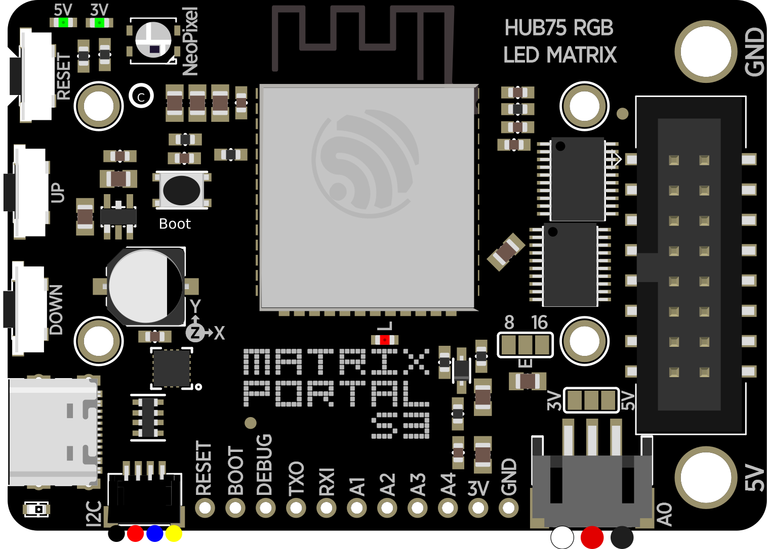
Pin Configuration and Descriptions

The Matrix Portal S3 features a set of pins designed for easy connection to HUB75 LED matrices and other peripherals. Below is the pin configuration:

Pin Name Description
GND Ground connection
5V 5V power input/output
HUB75 Data Data pins for connecting to HUB75 RGB LED matrices
USB-C USB-C port for power and programming
STEMMA QT I2C connector for additional sensors and peripherals
Button A User-programmable button A
Button B User-programmable button B
RGB LED Built-in RGB status LED

Usage Instructions

The Matrix Portal S3 is designed to simplify the process of driving LED matrices. Follow the steps below to get started:

Step 1: Powering the Board

  • Connect the Matrix Portal S3 to a 5V power source using the USB-C port or an external power supply.
  • Ensure the LED matrix is also powered using a compatible 5V power source.

Step 2: Programming the Board

  • Install CircuitPython on the Matrix Portal S3 by following the official Adafruit guide.
  • Once CircuitPython is installed, the board will appear as a USB drive on your computer.
  • Copy your CircuitPython code and any required libraries to the board.

Step 3: Connecting the LED Matrix

  • Plug the HUB75 connector from the LED matrix into the Matrix Portal S3.
  • Ensure the orientation of the connector matches the pin labels on the board.

Step 4: Writing Code

Below is an example CircuitPython code snippet to display scrolling text on an LED matrix:

import board
import displayio
from adafruit_matrixportal.matrixportal import MatrixPortal

Create a MatrixPortal object to manage the LED matrix

matrixportal = MatrixPortal(status_neopixel=board.NEOPIXEL, debug=True)

Set the text to display

matrixportal.set_text("Hello, World!", index=0)

Set the text color

matrixportal.set_text_color(0xFF00FF, index=0) # Purple color

while True: # The MatrixPortal library handles the display loop automatically pass


Best Practices

  • Use a high-quality 5V power supply to ensure stable operation of the LED matrix.
  • Avoid exceeding the current rating of your power supply, especially for large LED matrices.
  • Securely connect the HUB75 cable to prevent data transmission issues.
  • Use the STEMMA QT connector to easily add sensors or other peripherals to your project.

Troubleshooting and FAQs

Common Issues and Solutions

  1. LED Matrix Not Lighting Up

    • Ensure the HUB75 connector is securely plugged into the Matrix Portal S3.
    • Verify that the LED matrix is powered with a compatible 5V power supply.
    • Check your code for errors and ensure the correct libraries are installed.
  2. Wi-Fi Connection Fails

    • Double-check your Wi-Fi credentials in the code.
    • Ensure the Wi-Fi network is 2.4 GHz, as the ESP32-S3 does not support 5 GHz networks.
  3. Board Not Recognized by Computer

    • Verify that the USB-C cable supports data transfer (not just charging).
    • Try a different USB port or cable.
    • Reset the board by pressing the reset button.
  4. Scrolling Text Appears Garbled

    • Confirm that the LED matrix is compatible with the HUB75 standard.
    • Check the orientation of the HUB75 connector.
    • Ensure the text color and font settings in your code are correct.

FAQs

Q: Can I use Arduino instead of CircuitPython?
A: Yes, the Matrix Portal S3 is compatible with Arduino. Install the necessary ESP32-S3 board support package and libraries to get started.

Q: What is the maximum size of the LED matrix I can use?
A: The maximum size depends on the power supply and the refresh rate you require. Larger matrices may require additional power and careful optimization of your code.

Q: Can I connect multiple LED matrices?
A: Yes, you can chain multiple HUB75-compatible LED matrices, but ensure your power supply can handle the increased current draw.

Q: How do I update the firmware?
A: Download the latest UF2 firmware file from the Adafruit website and copy it to the board while in bootloader mode.

By following this documentation, you can effectively use the Matrix Portal S3 to create stunning LED matrix projects with ease!