How to Use ClearCore: Examples, Pinouts, and Specs
Introduction
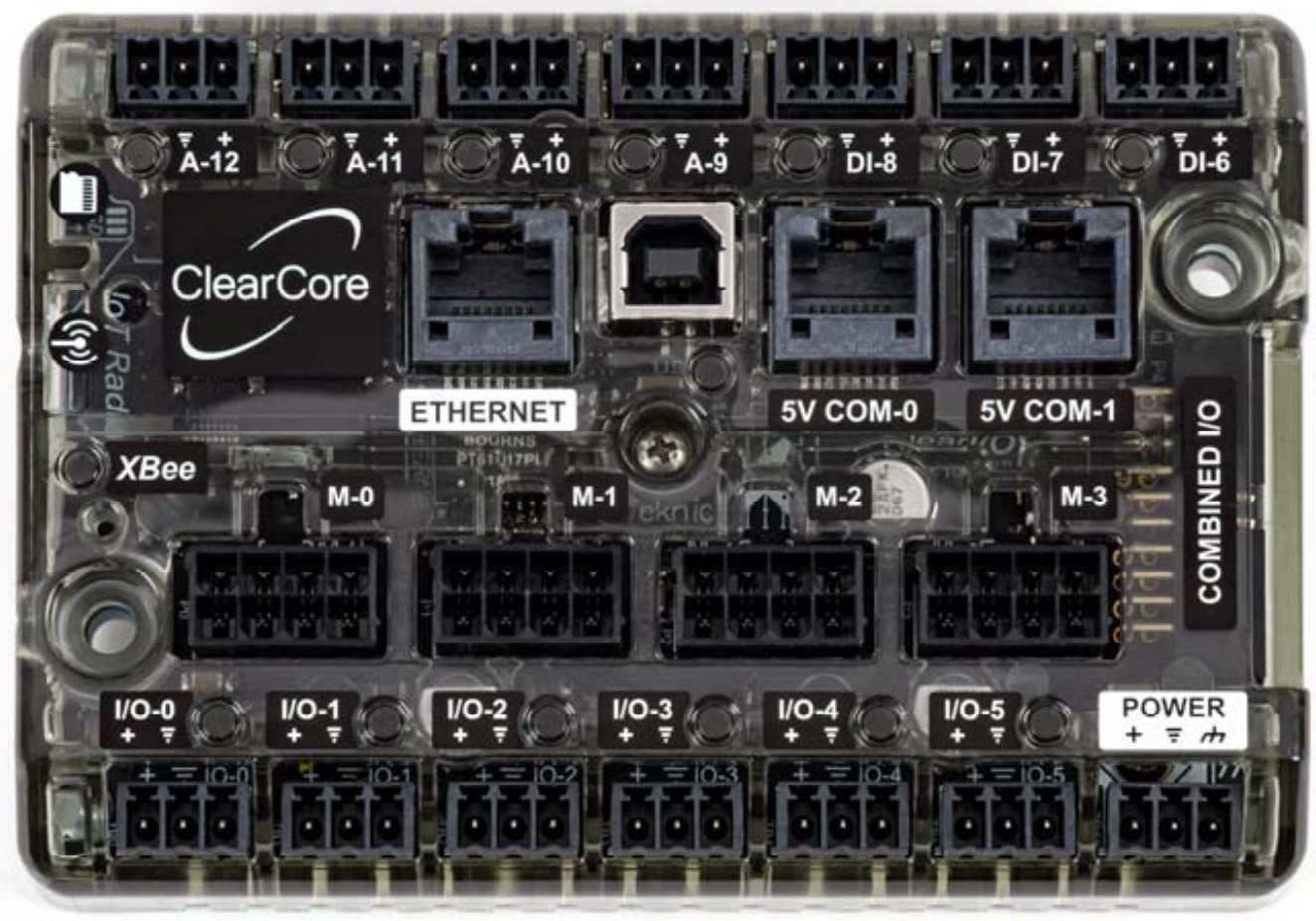
The ClearCore (CCIO-8), manufactured by Teknic, is a versatile microcontroller platform designed for robotics, industrial automation, and other control system applications. It features multiple I/O ports, supports various programming languages (including C++ and Arduino-style programming), and is compatible with a wide range of sensors, actuators, and motor controllers. Its robust design and flexibility make it ideal for developing complex, high-performance control systems.
Explore Projects Built with ClearCore

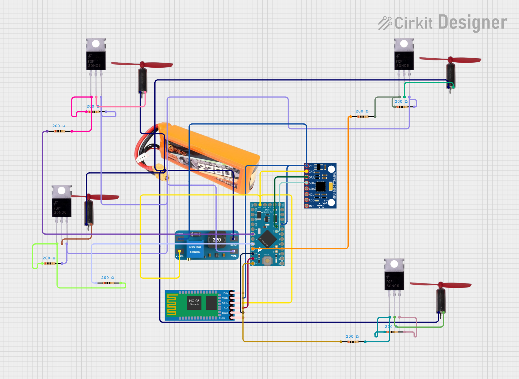
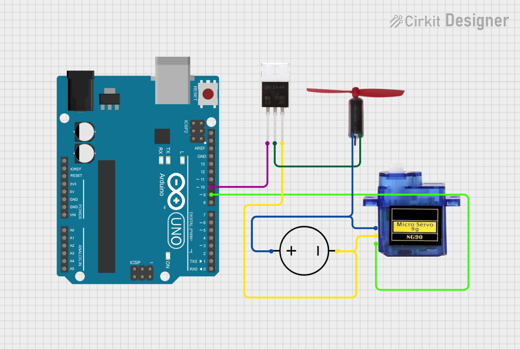
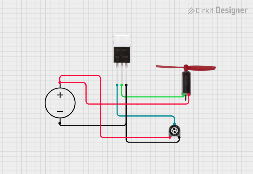
Explore Projects Built with ClearCore
Common Applications and Use Cases
- Robotics and motion control systems
- Industrial automation and process control
- Sensor data acquisition and processing
- Actuator control for precision systems
- Integration with ClearPath servo motors and other Teknic products
Technical Specifications
Key Technical Details
- Microcontroller: ARM Cortex-M4F, 32-bit, 120 MHz
- Operating Voltage: 24 VDC nominal (20–28 VDC range)
- Digital I/O: 8 configurable digital I/O ports
- Analog Inputs: 4 analog input channels (12-bit resolution)
- Communication Interfaces: USB, RS-232, CAN, Modbus RTU
- Programming Languages: C++, Arduino-style programming
- Dimensions: 4.25" x 3.25" x 1.0" (108 mm x 83 mm x 25 mm)
- Operating Temperature: 0°C to 50°C
Pin Configuration and Descriptions
The ClearCore features multiple connectors for I/O, power, and communication. Below is a summary of the key pin configurations:
Digital I/O Ports
| Pin | Name | Type | Description |
|---|---|---|---|
| 1 | IO-1 | Digital I/O | Configurable as input or output |
| 2 | IO-2 | Digital I/O | Configurable as input or output |
| 3 | IO-3 | Digital I/O | Configurable as input or output |
| 4 | IO-4 | Digital I/O | Configurable as input or output |
| 5 | IO-5 | Digital I/O | Configurable as input or output |
| 6 | IO-6 | Digital I/O | Configurable as input or output |
| 7 | IO-7 | Digital I/O | Configurable as input or output |
| 8 | IO-8 | Digital I/O | Configurable as input or output |
Analog Input Ports
| Pin | Name | Type | Description |
|---|---|---|---|
| 1 | AIN-1 | Analog Input | 12-bit resolution, 0–3.3V range |
| 2 | AIN-2 | Analog Input | 12-bit resolution, 0–3.3V range |
| 3 | AIN-3 | Analog Input | 12-bit resolution, 0–3.3V range |
| 4 | AIN-4 | Analog Input | 12-bit resolution, 0–3.3V range |
Power and Communication
| Pin | Name | Type | Description |
|---|---|---|---|
| 1 | VIN | Power Input | 24 VDC nominal (20–28 VDC range) |
| 2 | GND | Ground | Common ground |
| 3 | USB | Communication | USB interface for programming and data transfer |
| 4 | RS-232 | Communication | Serial communication interface |
| 5 | CAN | Communication | CAN bus interface for industrial communication |
Usage Instructions
How to Use the ClearCore in a Circuit
- Power the ClearCore: Connect a 24 VDC power supply to the VIN and GND pins.
- Connect I/O Devices: Attach sensors, actuators, or other devices to the digital I/O or analog input ports as needed.
- Establish Communication: Use the USB port for programming or data transfer. For industrial communication, connect to the RS-232 or CAN interface.
- Program the ClearCore: Write and upload your code using the ClearCore library and your preferred IDE (e.g., Arduino IDE or a C++ development environment).
- Test and Debug: Verify the functionality of your circuit and troubleshoot any issues.
Important Considerations and Best Practices
- Power Supply: Ensure the power supply voltage is within the specified range (20–28 VDC) to avoid damage.
- I/O Configuration: Configure digital I/O ports as inputs or outputs in your code before use.
- Analog Inputs: Use sensors with a 0–3.3V output range to ensure accurate readings.
- Communication Protocols: Select the appropriate communication protocol (USB, RS-232, or CAN) based on your application requirements.
- Grounding: Ensure all devices share a common ground to prevent communication or signal issues.
Example Code for Arduino UNO Integration
Below is an example of how to use the ClearCore with an Arduino UNO to read an analog sensor value and control a digital output:
// Include the ClearCore library
#include "ClearCore.h"

// Define the analog input and digital output pins
#define ANALOG_INPUT_PIN AIN_1 // Analog input pin on ClearCore
#define DIGITAL_OUTPUT_PIN IO_1 // Digital output pin on ClearCore

void setup() {
  // Initialize the ClearCore library
  ClearCoreInit();

  // Configure the digital output pin as an output
  DigitalOut(DIGITAL_OUTPUT_PIN).Mode(OUTPUT);

  // Configure the analog input pin
  AnalogIn(ANALOG_INPUT_PIN).Mode(INPUT);
}

void loop() {
  // Read the analog input value (0–4095 for 12-bit resolution)
  int sensorValue = AnalogIn(ANALOG_INPUT_PIN).Value();

  // If the sensor value exceeds a threshold, turn on the digital output
  if (sensorValue > 2000) {
    DigitalOut(DIGITAL_OUTPUT_PIN).State(HIGH); // Turn on output
  } else {
    DigitalOut(DIGITAL_OUTPUT_PIN).State(LOW); // Turn off output
  }

  // Add a small delay for stability
  delay(100);
}
Troubleshooting and FAQs
Common Issues and Solutions
ClearCore Not Powering On
- Cause: Insufficient or incorrect power supply.
- Solution: Verify that the power supply provides 24 VDC and is connected to the VIN and GND pins.
I/O Ports Not Responding
- Cause: Incorrect configuration in the code.
- Solution: Ensure that each I/O port is properly configured as input or output in your program.
Analog Input Readings Are Inaccurate
- Cause: Sensor output voltage exceeds the 0–3.3V range.
- Solution: Use a voltage divider or level shifter to scale the sensor output to the appropriate range.
Communication Issues
- Cause: Incorrect wiring or protocol mismatch.
- Solution: Double-check the wiring and ensure the correct communication protocol is selected in your code.
FAQs
Can I use the ClearCore with third-party sensors and actuators? Yes, the ClearCore is compatible with a wide range of third-party devices, provided they meet the voltage and communication requirements.
What IDEs are supported for programming the ClearCore? The ClearCore can be programmed using the Arduino IDE or any C++ development environment that supports the ClearCore library.
Is the ClearCore compatible with Teknic ClearPath motors? Yes, the ClearCore is designed to integrate seamlessly with Teknic ClearPath servo motors for advanced motion control applications.