How to Use MKR Relay Shield: Examples, Pinouts, and Specs
Introduction
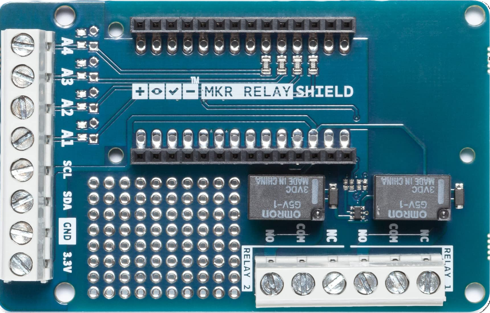
The MKR Relay Shield (Manufacturer Part ID: TSX00003) is an add-on board designed for use with Arduino MKR series boards. It enables users to control high-voltage devices such as appliances, lights, and other electronic equipment. The shield features two independent relays, allowing for safe and efficient switching of devices that operate at higher voltages and currents than typical microcontroller outputs can handle.
Explore Projects Built with MKR Relay Shield
Explore Projects Built with MKR Relay Shield
Common Applications and Use Cases
- Home automation systems (e.g., controlling lights, fans, or appliances)
- Industrial automation and control
- IoT projects requiring high-voltage device control
- Prototyping and testing of relay-based circuits
Technical Specifications
The MKR Relay Shield is designed to interface seamlessly with Arduino MKR boards. Below are its key technical details:
General Specifications
| Parameter | Value |
|---|---|
| Operating Voltage | 5V (powered via MKR board) |
| Relay Channels | 2 |
| Maximum Switching Voltage | 220V AC / 30V DC |
| Maximum Switching Current | 2A |
| Communication Interface | Digital I/O pins |
| Dimensions | 61.5mm x 25mm x 20mm |
Pin Configuration and Descriptions
The MKR Relay Shield connects directly to the Arduino MKR board via its headers. Below is the pin configuration for the relay terminals:
| Pin Name | Description |
|---|---|
| NO1 (Normally Open 1) | Normally open terminal for Relay 1. Connect the load here for switching. |
| COM1 (Common 1) | Common terminal for Relay 1. Connect the power source or ground here. |
| NC1 (Normally Closed 1) | Normally closed terminal for Relay 1. Load is connected when relay is off. |
| NO2 (Normally Open 2) | Normally open terminal for Relay 2. Connect the load here for switching. |
| COM2 (Common 2) | Common terminal for Relay 2. Connect the power source or ground here. |
| NC2 (Normally Closed 2) | Normally closed terminal for Relay 2. Load is connected when relay is off. |
Control Pins (Arduino MKR Board)
| Arduino Pin | Function |
|---|---|
| D1 | Controls Relay 1 |
| D2 | Controls Relay 2 |
Usage Instructions
How to Use the MKR Relay Shield in a Circuit
- Attach the Shield: Plug the MKR Relay Shield directly onto the Arduino MKR board. Ensure the headers are aligned properly.
- Connect the Load:
- For each relay, connect the load to the
NO(Normally Open) terminal and the power source to theCOM(Common) terminal. - If you want the load to be powered when the relay is off, use the
NC(Normally Closed) terminal instead ofNO.
- For each relay, connect the load to the
- Power the System: Power the Arduino MKR board via USB or an external power source. The shield will draw power from the MKR board.
- Control the Relays: Use digital pins D1 and D2 on the MKR board to control Relay 1 and Relay 2, respectively.
Important Considerations and Best Practices
- Voltage and Current Ratings: Do not exceed the maximum switching voltage (220V AC / 30V DC) or current (2A) for each relay.
- Isolation: Ensure proper isolation between the high-voltage side (relay terminals) and the low-voltage side (Arduino MKR board) to avoid damage or hazards.
- External Power: If controlling high-power devices, consider using an external power source for the load to avoid overloading the Arduino board.
- Code Logic: Use appropriate delay intervals in your code to prevent rapid switching of the relays, which can cause wear and tear.
Example Code for Arduino MKR Board
Below is an example sketch to control the relays using an Arduino MKR board:
// Example code to control the MKR Relay Shield
// Relay 1 is connected to pin D1, and Relay 2 is connected to pin D2.

#define RELAY1_PIN 1  // Digital pin for Relay 1
#define RELAY2_PIN 2  // Digital pin for Relay 2

void setup() {
  // Initialize relay pins as outputs
  pinMode(RELAY1_PIN, OUTPUT);
  pinMode(RELAY2_PIN, OUTPUT);

  // Start with both relays off
  digitalWrite(RELAY1_PIN, LOW);
  digitalWrite(RELAY2_PIN, LOW);
}

void loop() {
  // Turn on Relay 1
  digitalWrite(RELAY1_PIN, HIGH);
  delay(2000); // Keep Relay 1 on for 2 seconds

  // Turn off Relay 1 and turn on Relay 2
  digitalWrite(RELAY1_PIN, LOW);
  digitalWrite(RELAY2_PIN, HIGH);
  delay(2000); // Keep Relay 2 on for 2 seconds

  // Turn off both relays
  digitalWrite(RELAY2_PIN, LOW);
  delay(2000); // Wait for 2 seconds before repeating
}
Troubleshooting and FAQs
Common Issues and Solutions
Relays Not Switching
- Cause: Incorrect wiring or insufficient power supply.
- Solution: Double-check the wiring of the load and ensure the Arduino MKR board is powered properly.
Arduino Board Resets When Relays Switch
- Cause: High inrush current from the load.
- Solution: Use a separate power supply for the load or add a flyback diode across the relay terminals.
Relays Stuck in One State
- Cause: Faulty relay or incorrect control signal.
- Solution: Verify the control signals from the Arduino board and test the relay with a multimeter.
Load Not Turning On/Off
- Cause: Incorrect connection to the relay terminals.
- Solution: Ensure the load is connected to the correct terminals (
NO,NC, andCOM) based on the desired behavior.
FAQs
Q: Can I use the MKR Relay Shield with non-MKR Arduino boards?
A: The shield is specifically designed for MKR boards. While it may be possible to adapt it for other boards, it is not recommended due to pin alignment and power compatibility issues.
Q: Is the MKR Relay Shield suitable for controlling motors?
A: The shield can control small motors within the 2A current limit. For larger motors, use a motor driver or an external relay module.
Q: Can I stack other shields on top of the MKR Relay Shield?
A: Stacking is possible, but ensure the additional shield does not interfere with the relay terminals or exceed the power capacity of the MKR board.
Q: How do I know if a relay is active?
A: The MKR Relay Shield includes onboard LEDs that light up when a relay is activated.