How to Use PZEM-017 small: Examples, Pinouts, and Specs

Introduction
The PZEM-017 Small is a compact and versatile module designed for measuring various electrical parameters in AC circuits. This module can accurately measure voltage, current, power, and energy, making it an essential tool for monitoring and managing electrical systems. Its small size and ease of integration make it suitable for a wide range of applications, including home automation, industrial monitoring, and energy management systems.
Explore Projects Built with PZEM-017 small


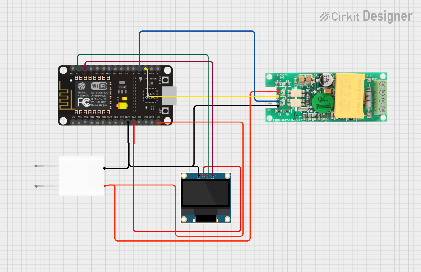
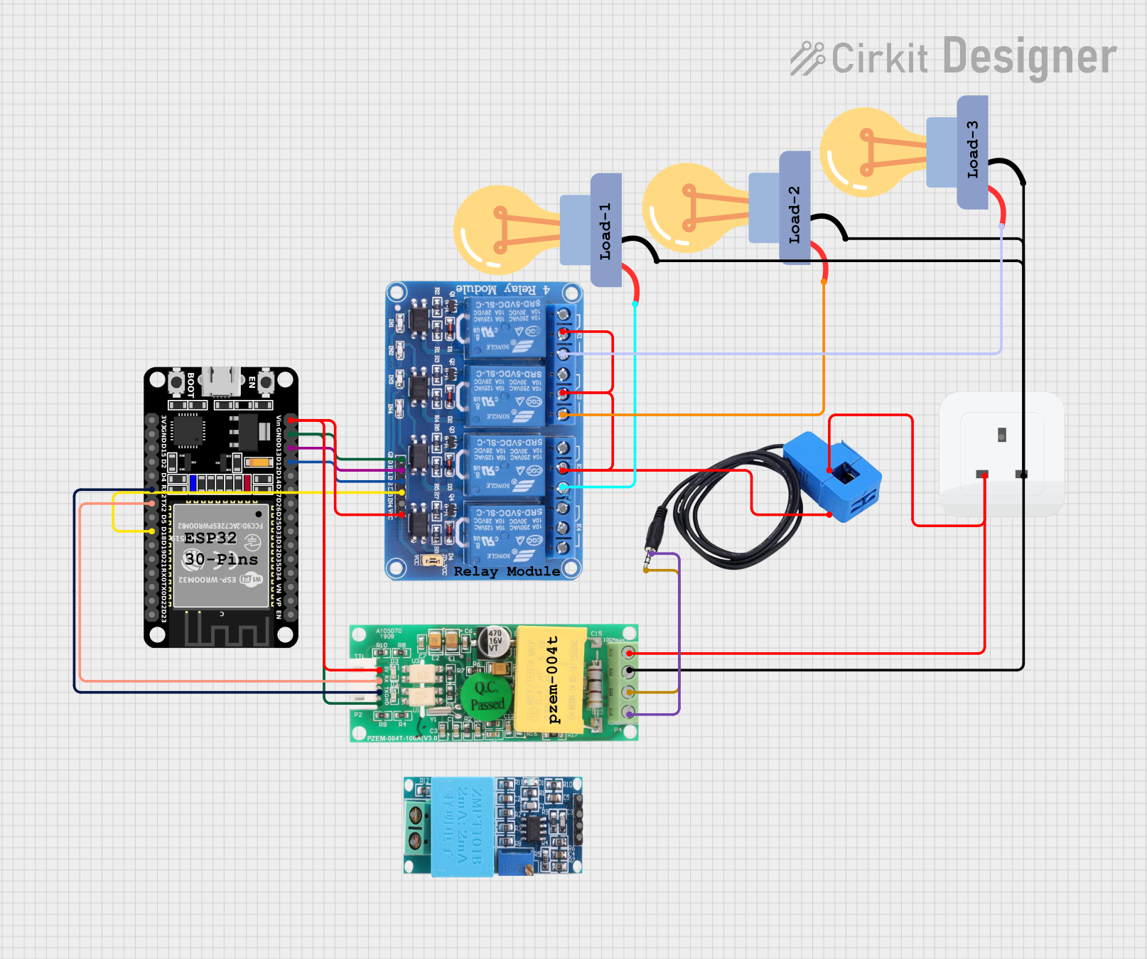
Explore Projects Built with PZEM-017 small
Technical Specifications
Key Technical Details
| Parameter | Value |
|---|---|
| Voltage Range | 80-260V AC |
| Current Range | 0-100A (with external CT) |
| Power Range | 0-22kW |
| Energy Range | 0-9999kWh |
| Frequency Range | 45-65Hz |
| Accuracy | ±1% |
| Communication | RS485 |
| Power Supply | 5V DC |
Pin Configuration and Descriptions
| Pin Number | Pin Name | Description |
|---|---|---|
| 1 | VCC | Power supply input (5V DC) |
| 2 | GND | Ground |
| 3 | A | RS485 communication line A |
| 4 | B | RS485 communication line B |
| 5 | V+ | Voltage measurement input (connected to AC line) |
| 6 | V- | Voltage measurement input (connected to AC line) |
| 7 | I+ | Current measurement input (connected to CT) |
| 8 | I- | Current measurement input (connected to CT) |
Usage Instructions
How to Use the PZEM-017 Small in a Circuit
Power Supply Connection:
- Connect the VCC pin to a 5V DC power supply.
- Connect the GND pin to the ground of the power supply.
Voltage Measurement:
- Connect the V+ and V- pins to the AC line where voltage measurement is required.
Current Measurement:
- Connect the I+ and I- pins to the current transformer (CT) for current measurement.
Communication:
- Connect the A and B pins to the RS485 communication lines for data transmission.
Important Considerations and Best Practices
- Ensure that the module is powered with a stable 5V DC supply to avoid measurement inaccuracies.
- Use appropriate current transformers (CTs) for accurate current measurement.
- Properly insulate all connections to prevent electrical hazards.
- Follow the manufacturer's guidelines for RS485 communication to ensure reliable data transmission.
Troubleshooting and FAQs
Common Issues and Solutions
No Data Output:
- Solution: Check the power supply connections and ensure the module is receiving 5V DC. Verify the RS485 communication lines are correctly connected.
Inaccurate Measurements:
- Solution: Ensure the voltage and current connections are secure and properly insulated. Use the recommended CT for current measurement.
Communication Errors:
- Solution: Verify the RS485 communication settings (baud rate, parity, etc.) match between the module and the receiving device.
FAQs
Q1: Can the PZEM-017 Small measure DC parameters?
- No, the PZEM-017 Small is designed for AC measurements only.
Q2: What is the maximum current the module can measure?
- The module can measure up to 100A with an appropriate current transformer (CT).
Q3: How do I reset the energy measurement?
- Refer to the manufacturer's documentation for the specific command to reset the energy measurement via RS485 communication.
Example Code for Arduino UNO
Below is an example code to interface the PZEM-017 Small with an Arduino UNO using RS485 communication.
#include <SoftwareSerial.h>

// Define the RS485 communication pins
#define RX_PIN 10
#define TX_PIN 11

SoftwareSerial rs485Serial(RX_PIN, TX_PIN);

void setup() {
  // Initialize serial communication
  Serial.begin(9600);
  rs485Serial.begin(9600);

  // Print a message to indicate setup is complete
  Serial.println("PZEM-017 Small Module Setup Complete");
}

void loop() {
  // Request data from the PZEM-017 module
  rs485Serial.write(0x01); // Example command to request data

  // Wait for a response
  delay(100);

  // Check if data is available
  if (rs485Serial.available()) {
    // Read and print the data
    while (rs485Serial.available()) {
      byte data = rs485Serial.read();
      Serial.print(data, HEX);
      Serial.print(" ");
    }
    Serial.println();
  }

  // Wait before the next request
  delay(1000);
}
This code sets up RS485 communication between the Arduino UNO and the PZEM-017 Small module. It sends a request to the module and prints the received data to the Serial Monitor. Adjust the command and data handling as per the specific requirements of your application.