Cirkit Designer Logo
Cirkit Designer
Your all-in-one circuit design IDE
Home / 
Component Documentation

How to Use WS2815 LED Strip: Examples, Pinouts, and Specs

Image of WS2815 LED Strip
Cirkit Designer LogoDesign with WS2815 LED Strip in Cirkit Designer

Introduction

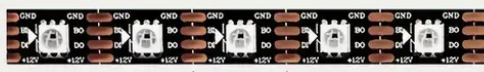
The WS2815 LED strip is a high-performance, individually addressable LED strip that allows for full-color and brightness control of each LED in the array. Manufactured by Heng Tu, the WS2815 DC12V is an upgrade from its predecessor, the WS2812B, offering dual-signal wires, which provides improved signal reliability and allows for continuous operation even if one LED fails. Common applications include decorative lighting, signage, and complex lighting displays for both indoor and outdoor environments.

Explore Projects Built with WS2815 LED Strip

Use Cirkit Designer to design, explore, and prototype these projects online. Some projects support real-time simulation. Click "Open Project" to start designing instantly!
Arduino Mega 2560 and Raspberry Pi 4B Controlled WS2812 RGB LED Strip
Image of circuit_image: A project utilizing WS2815 LED Strip in a practical application
This circuit features an Arduino Mega 2560 microcontroller programmed to control a WS2812 RGB LED strip and a white LED, indicating status or providing user feedback. The Arduino and the LED strip are powered by a common 5V supply, and the circuit includes interfacing with a Raspberry Pi 4B for potential communication or coordination between the two boards.
Cirkit Designer LogoOpen Project in Cirkit Designer
Arduino UNO Controlled WS2812 RGB LED Strip with Custom Color Patterns
Image of LED: A project utilizing WS2815 LED Strip in a practical application
This circuit consists of an Arduino UNO microcontroller connected to a WS2812 RGB LED strip. The Arduino controls the LED strip by sending data signals through pin D8, while the 5V and GND pins provide power. The provided code initializes the LED strip and sets specific colors to the first three LEDs.
Cirkit Designer LogoOpen Project in Cirkit Designer
Wi-Fi Controlled LED Strip with Wemos D1 Mini and IKEA Trådfri Driver
Image of WLED Diskbänken: A project utilizing WS2815 LED Strip in a practical application
This circuit is designed to control a WS2812 RGB LED strip using a Wemos D1 Mini microcontroller running WLED software. The circuit includes an IKEA Trådfri LED driver that converts 24V to 5V via an LM2596 voltage regulator, and an nMOS transistor to switch the LED strip's ground connection. The setup is intended for lighting applications, such as under-cabinet lighting in a kitchen.
Cirkit Designer LogoOpen Project in Cirkit Designer
ESP32-Controlled WS2812 RGB LED Strip Lighting System
Image of Test: A project utilizing WS2815 LED Strip in a practical application
This circuit is designed to control a WS2812 RGB LED strip using an ESP32 microcontroller. The 5V DC power supply provides power to both the ESP32 and the LED strip. The ESP32's digital pin (D13) is connected to the LED strip's data input (DIN) to enable programmable control of the LED colors and patterns.
Cirkit Designer LogoOpen Project in Cirkit Designer

Explore Projects Built with WS2815 LED Strip

Use Cirkit Designer to design, explore, and prototype these projects online. Some projects support real-time simulation. Click "Open Project" to start designing instantly!
Image of circuit_image: A project utilizing WS2815 LED Strip in a practical application
Arduino Mega 2560 and Raspberry Pi 4B Controlled WS2812 RGB LED Strip
This circuit features an Arduino Mega 2560 microcontroller programmed to control a WS2812 RGB LED strip and a white LED, indicating status or providing user feedback. The Arduino and the LED strip are powered by a common 5V supply, and the circuit includes interfacing with a Raspberry Pi 4B for potential communication or coordination between the two boards.
Cirkit Designer LogoOpen Project in Cirkit Designer
Image of LED: A project utilizing WS2815 LED Strip in a practical application
Arduino UNO Controlled WS2812 RGB LED Strip with Custom Color Patterns
This circuit consists of an Arduino UNO microcontroller connected to a WS2812 RGB LED strip. The Arduino controls the LED strip by sending data signals through pin D8, while the 5V and GND pins provide power. The provided code initializes the LED strip and sets specific colors to the first three LEDs.
Cirkit Designer LogoOpen Project in Cirkit Designer
Image of WLED Diskbänken: A project utilizing WS2815 LED Strip in a practical application
Wi-Fi Controlled LED Strip with Wemos D1 Mini and IKEA Trådfri Driver
This circuit is designed to control a WS2812 RGB LED strip using a Wemos D1 Mini microcontroller running WLED software. The circuit includes an IKEA Trådfri LED driver that converts 24V to 5V via an LM2596 voltage regulator, and an nMOS transistor to switch the LED strip's ground connection. The setup is intended for lighting applications, such as under-cabinet lighting in a kitchen.
Cirkit Designer LogoOpen Project in Cirkit Designer
Image of Test: A project utilizing WS2815 LED Strip in a practical application
ESP32-Controlled WS2812 RGB LED Strip Lighting System
This circuit is designed to control a WS2812 RGB LED strip using an ESP32 microcontroller. The 5V DC power supply provides power to both the ESP32 and the LED strip. The ESP32's digital pin (D13) is connected to the LED strip's data input (DIN) to enable programmable control of the LED colors and patterns.
Cirkit Designer LogoOpen Project in Cirkit Designer

Technical Specifications

Key Technical Details

  • Voltage: 12V DC
  • Current: 18.5mA per LED (typical)
  • Power Consumption: 0.22W per LED (typical)
  • LED Type: RGB SMD5050
  • Color Depth: 24-bit (8 bits per channel)
  • IC Type: Built-in WS2815
  • Cuttable: Every LED is cuttable
  • Data Transfer Speed: 800 Kbps (typical)

Pin Configuration and Descriptions

Pin Number Name Description
1 VDD Power supply (12V)
2 DOUT Data output to the next LED
3 GND Ground connection
4 DIN Data input from the controller
5 BIN Backup data input

Usage Instructions

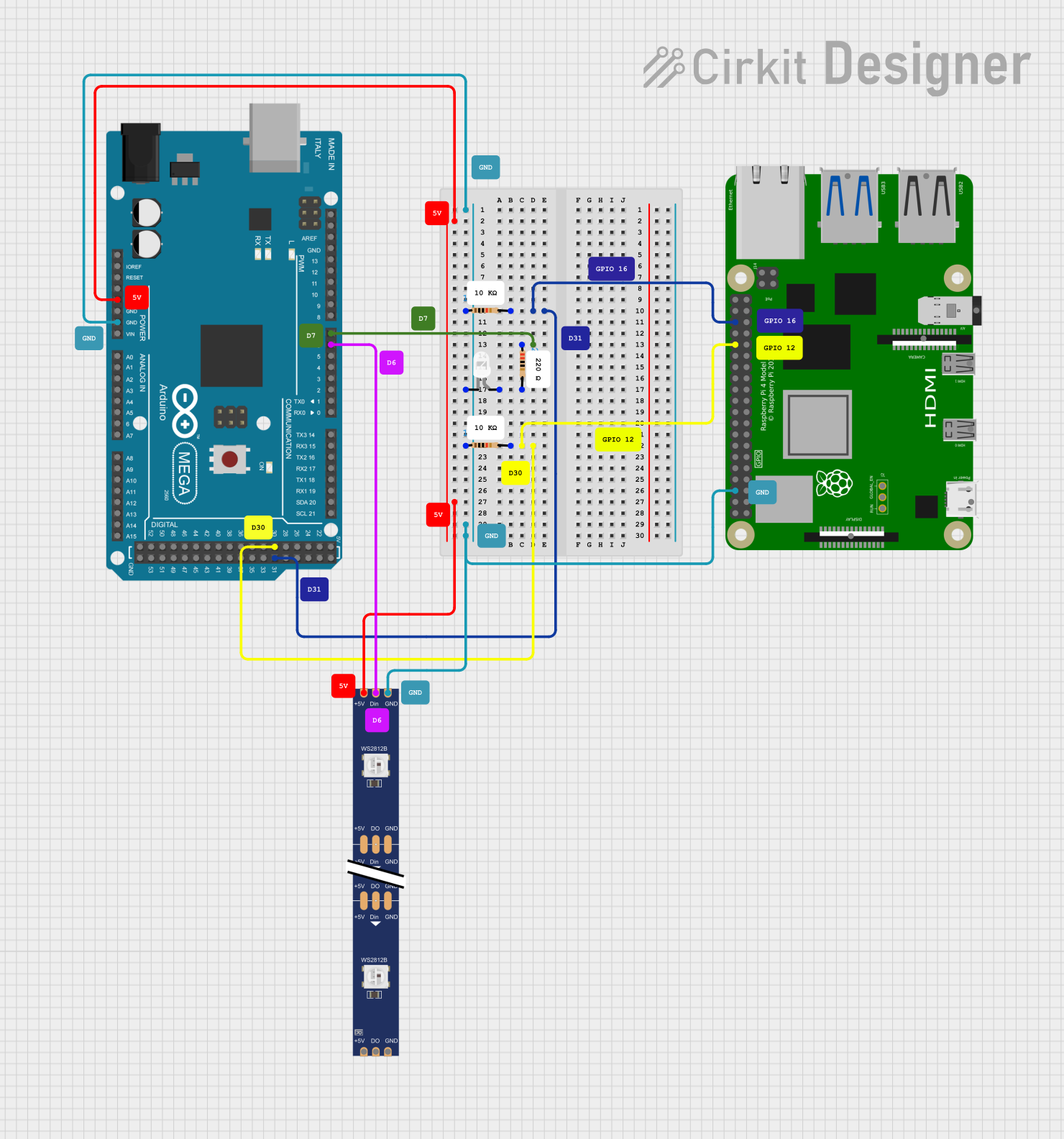
Connecting to a Circuit

  1. Power Supply: Connect the VDD pin to a 12V power supply and the GND pin to the ground. Ensure that the power supply can handle the current required for the number of LEDs you intend to use.
  2. Data Signal: Connect the DIN pin to the data output pin of your LED controller. If you're using an Arduino, this will typically be a digital I/O pin.
  3. Backup Data Signal: Connect the BIN pin to the data output pin of your LED controller, or leave it unconnected if not used.
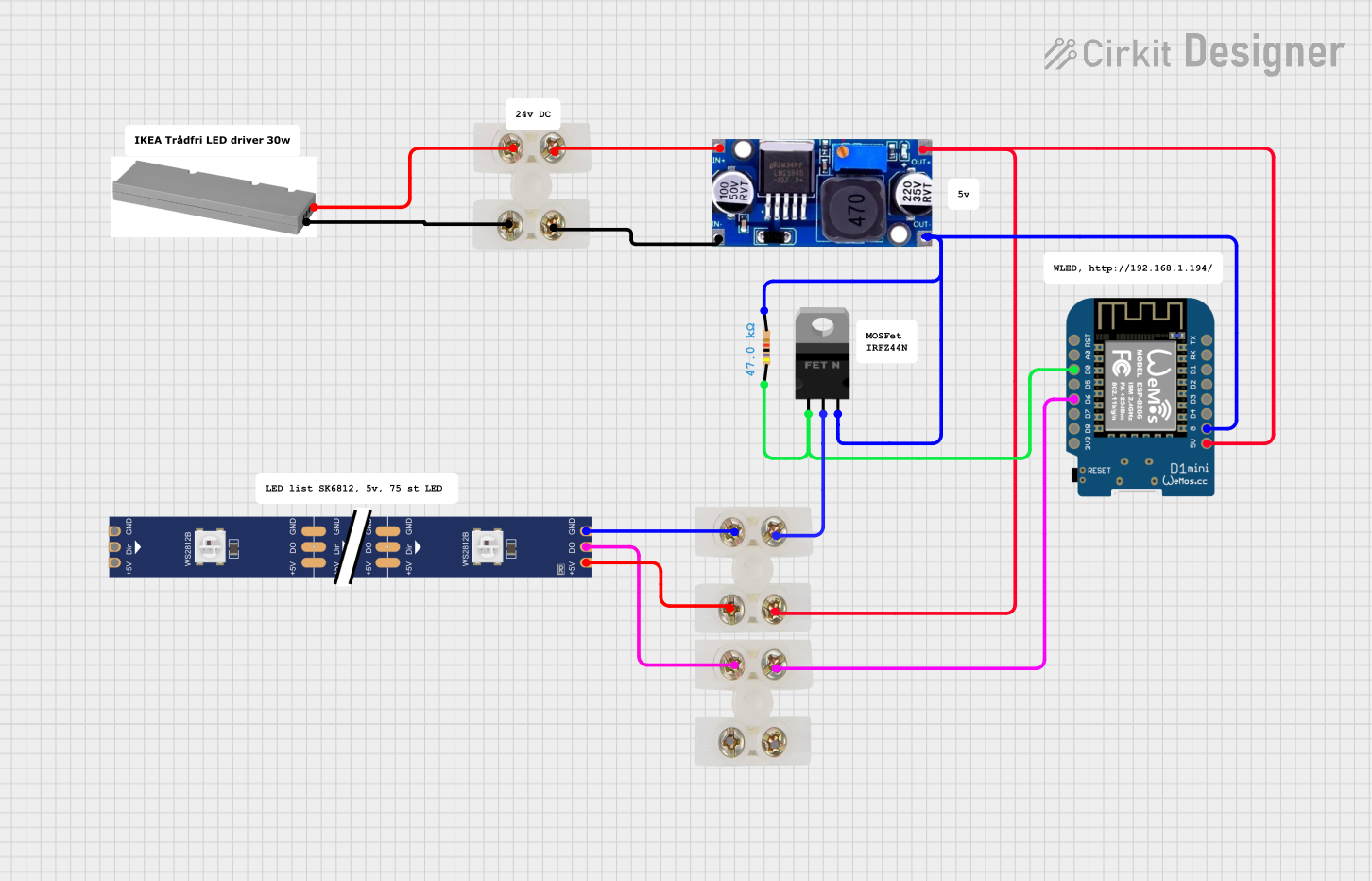
Best Practices

  • Use a capacitor (typically 1000 µF, 16V) across the power supply pins to prevent initial onrush of current from damaging the LEDs.
  • Add a 300 to 500 Ohm resistor on the data input line to reduce noise on the data signal.
  • Ensure that the ground of the LED strip is connected to the ground of the LED controller to prevent potential damage from voltage spikes.
  • When extending the strip, make sure to reinforce the power supply at various points to prevent voltage drop.

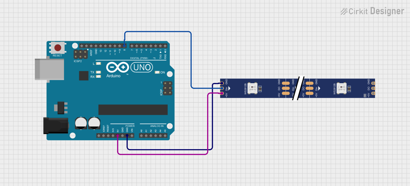
Example Code for Arduino UNO

#include <Adafruit_NeoPixel.h>

#define LED_PIN     6 // The pin where the data line is connected
#define LED_COUNT  30 // Number of LEDs in the strip

// Initialize the NeoPixel library.
Adafruit_NeoPixel strip(LED_COUNT, LED_PIN, NEO_GRB + NEO_KHZ800);

void setup() {
  strip.begin();           // Initialize the strip
  strip.show();            // Initialize all pixels to 'off'
}

void loop() {
  // Simple chase effect
  for(int i=0; i<strip.numPixels(); i++) {
    strip.setPixelColor(i, strip.Color(255, 0, 0)); // Red color
    strip.show();
    delay(50);
    strip.setPixelColor(i, strip.Color(0, 0, 0));   // Turn off
  }
}

Troubleshooting and FAQs

Common Issues

  • LEDs Not Lighting Up: Check the power supply and connections. Ensure the data line is connected to the correct pin and that the ground is shared between the LED strip and the controller.
  • Flickering LEDs: This can be due to a poor power supply or long data lines. Shorten the data line or add a level shifter to boost the signal.
  • One LED is Out, but the Rest Work: This is a feature of the WS2815. Check the individual LED for physical damage. The rest of the strip should continue to function due to the dual-signal design.

FAQs

Q: Can I control the WS2815 LED strip with any microcontroller? A: Yes, as long as the microcontroller has a digital output capable of 800 Kbps data speed.

Q: How many LEDs can I control with a single Arduino UNO? A: The limit is based on the Arduino's memory and the power supply. Each LED requires 3 bytes of RAM, so an Arduino UNO can control up to 2,000 LEDs given adequate power and memory management.

Q: Do I need to use the backup data input? A: The backup data input (BIN) is optional. It provides redundancy, so if one LED fails, the signal can still pass through to the rest of the strip.

Q: How do I cut the LED strip? A: The strip can be cut at the designated cutting lines between the LEDs. Make sure to cut cleanly and seal any exposed ends to prevent shorts.