How to Use RTC DS1032: Examples, Pinouts, and Specs
Introduction
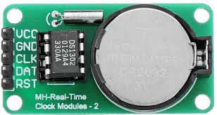
The RTC DS1032, manufactured by ENGLAB (Part ID: DS1302), is a real-time clock (RTC) integrated circuit designed to provide accurate timekeeping and date information. It features a built-in oscillator and operates on low power, making it ideal for battery-powered applications. The DS1032 communicates via the I2C interface, ensuring seamless integration with microcontrollers and other digital systems.
Explore Projects Built with RTC DS1032


Explore Projects Built with RTC DS1032
Common Applications and Use Cases
- Digital clocks and timers
- Data loggers
- Home automation systems
- Industrial control systems
- Wearable devices
- Battery-powered embedded systems
Technical Specifications
The following table outlines the key technical details of the RTC DS1032:
| Parameter | Value |
|---|---|
| Operating Voltage | 2.0V to 5.5V |
| Current Consumption | < 1 µA (at 3.0V, timekeeping mode) |
| Communication Protocol | I2C |
| Oscillator Frequency | 32.768 kHz |
| Time Format | 24-hour or 12-hour with AM/PM |
| Date Range | Year, Month, Date, Day |
| Temperature Range | -40°C to +85°C |
| Backup Battery Support | Yes |
Pin Configuration and Descriptions
The DS1032 has an 8-pin configuration. The table below describes each pin:
| Pin Number | Pin Name | Description |
|---|---|---|
| 1 | VCC | Main power supply (2.0V to 5.5V) |
| 2 | GND | Ground |
| 3 | SDA | Serial Data Line for I2C communication |
| 4 | SCL | Serial Clock Line for I2C communication |
| 5 | VBAT | Backup battery input for timekeeping during power loss |
| 6 | X1 | Oscillator input (connect to 32.768 kHz crystal) |
| 7 | X2 | Oscillator output (connect to 32.768 kHz crystal) |
| 8 | NC | No connection |
Usage Instructions
How to Use the Component in a Circuit
- Power Supply: Connect the VCC pin to a regulated power source (2.0V to 5.5V) and the GND pin to the ground.
- Backup Battery: Attach a coin-cell battery (e.g., CR2032) to the VBAT pin to ensure timekeeping during power outages.
- Oscillator: Connect a 32.768 kHz crystal between the X1 and X2 pins for accurate timekeeping.
- I2C Communication: Connect the SDA and SCL pins to the corresponding I2C pins on your microcontroller. Use pull-up resistors (typically 4.7 kΩ) on both lines.
Important Considerations and Best Practices
- Ensure the backup battery is properly connected to avoid losing time data during power interruptions.
- Use decoupling capacitors (e.g., 0.1 µF) near the VCC pin to reduce noise and improve stability.
- Avoid placing the crystal oscillator near high-frequency components to minimize interference.
- Verify the I2C address of the DS1032 in your system to prevent conflicts with other devices on the bus.
Example: Connecting the DS1032 to an Arduino UNO
Below is an example Arduino sketch to read the time and date from the DS1032:
#include <Wire.h> // Include the Wire library for I2C communication

#define DS1032_I2C_ADDRESS 0x68 // I2C address of the DS1032 RTC

void setup() {
  Wire.begin(); // Initialize I2C communication
  Serial.begin(9600); // Start serial communication for debugging
}

void loop() {
  Wire.beginTransmission(DS1032_I2C_ADDRESS); // Start communication with DS1032
  Wire.write(0x00); // Set register pointer to the first register
  Wire.endTransmission();

  Wire.requestFrom(DS1032_I2C_ADDRESS, 7); // Request 7 bytes (time and date)
  if (Wire.available() == 7) {
    byte seconds = Wire.read(); // Read seconds
    byte minutes = Wire.read(); // Read minutes
    byte hours = Wire.read();   // Read hours
    byte day = Wire.read();     // Read day of the week
    byte date = Wire.read();    // Read date
    byte month = Wire.read();   // Read month
    byte year = Wire.read();    // Read year

    // Convert BCD to decimal for display
    seconds = (seconds & 0x0F) + ((seconds >> 4) * 10);
    minutes = (minutes & 0x0F) + ((minutes >> 4) * 10);
    hours = (hours & 0x0F) + ((hours >> 4) * 10);
    date = (date & 0x0F) + ((date >> 4) * 10);
    month = (month & 0x0F) + ((month >> 4) * 10);
    year = (year & 0x0F) + ((year >> 4) * 10);

    // Print the time and date
    Serial.print("Time: ");
    Serial.print(hours);
    Serial.print(":");
    Serial.print(minutes);
    Serial.print(":");
    Serial.println(seconds);

    Serial.print("Date: ");
    Serial.print(date);
    Serial.print("/");
    Serial.print(month);
    Serial.print("/20");
    Serial.println(year);
  }

  delay(1000); // Wait for 1 second before reading again
}
Troubleshooting and FAQs
Common Issues and Solutions
The RTC is not keeping time when the main power is off.
- Ensure the backup battery is properly connected to the VBAT pin.
- Verify that the battery voltage is sufficient (e.g., 3.0V for a CR2032).
Incorrect time or date is being read.
- Check the I2C connections and ensure pull-up resistors are in place.
- Verify that the crystal oscillator is correctly connected and functioning.
The microcontroller cannot communicate with the DS1032.
- Confirm the I2C address (default: 0x68) matches the address in your code.
- Inspect the SDA and SCL connections for loose wires or poor soldering.
The RTC is drifting or losing accuracy.
- Ensure the crystal oscillator is of high quality and operates at 32.768 kHz.
- Avoid placing the RTC near high-frequency or noisy components.
FAQs
Q: Can the DS1032 operate without a backup battery?
A: Yes, but it will lose timekeeping functionality during power interruptions.
Q: What is the maximum length of the I2C bus for the DS1032?
A: The maximum length depends on the pull-up resistor values and capacitance of the bus. Typically, it should not exceed 1 meter for reliable communication.
Q: Can I use the DS1032 with a 3.3V microcontroller?
A: Yes, the DS1032 operates within a voltage range of 2.0V to 5.5V, making it compatible with 3.3V systems.