Cirkit Designer Logo
Cirkit Designer
Your all-in-one circuit design IDE
Home / 
Component Documentation

How to Use gear motor: Examples, Pinouts, and Specs

Image of gear motor
Cirkit Designer LogoDesign with gear motor in Cirkit Designer

Introduction

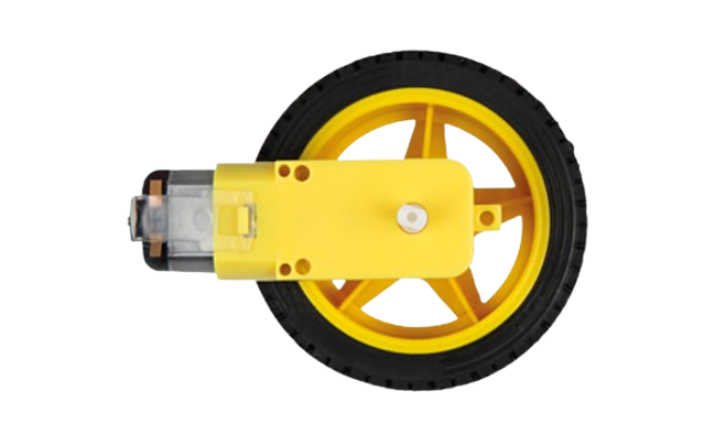
A gear motor is an electric motor integrated with a gear system to reduce speed and increase torque. This combination makes it ideal for applications requiring high torque at low speeds. Gear motors are widely used in robotics, conveyor systems, industrial machinery, and automotive applications. They are particularly valued for their ability to deliver precise motion control and power transmission.

Manufacturer: Rajesh Shah
Part ID: motor

Explore Projects Built with gear motor

Use Cirkit Designer to design, explore, and prototype these projects online. Some projects support real-time simulation. Click "Open Project" to start designing instantly!
Arduino-Controlled DC Motor with Encoder Feedback and Adjustable Speed
Image of gear motor: A project utilizing gear motor in a practical application
This circuit controls a gear motor with an integrated encoder using an L298N DC motor driver, which is interfaced with an Arduino Mega 2560 microcontroller. The motor's power is supplied by a 12V power source, which is also connected to an XL4015 DC Buck Step-down converter to provide a regulated 5V supply to the Arduino. The encoder outputs are connected to the Arduino for position or speed feedback, and the Arduino is programmed to manage the motor's speed and direction.
Cirkit Designer LogoOpen Project in Cirkit Designer
Battery-Powered Gear Motor Control with Rocker Switch
Image of Dish Washer: A project utilizing gear motor in a practical application
This circuit is a simple control circuit for a gear motor, powered by a 9V battery. The rocker switch is used to turn the motor on and off by completing or breaking the circuit between the battery and the motor. There is no microcontroller or complex logic involved, making it a straightforward power control circuit.
Cirkit Designer LogoOpen Project in Cirkit Designer
ESP32 and L298N Motor Driver Controlled Battery-Powered Robotic Car
Image of ESP 32 BT BOT: A project utilizing gear motor in a practical application
This circuit is a motor control system powered by a 12V battery, utilizing an L298N motor driver to control four DC gearmotors. An ESP32 microcontroller is used to send control signals to the motor driver, enabling precise control of the motors for applications such as a robotic vehicle.
Cirkit Designer LogoOpen Project in Cirkit Designer
Arduino-Controlled Bluetooth Robotic Vehicle with Ultrasonic Navigation
Image of BOAT 2: A project utilizing gear motor in a practical application
This circuit is designed to remotely control two DC gearmotors using an Arduino UNO and an L298N motor driver, with an HC-05 Bluetooth module for wireless communication. It includes a JSN-SR04T ultrasonic sensor for distance measurement and a TM1637 display for output. Power management is handled by an 18650 Li-Ion battery and rocker switches.
Cirkit Designer LogoOpen Project in Cirkit Designer

Explore Projects Built with gear motor

Use Cirkit Designer to design, explore, and prototype these projects online. Some projects support real-time simulation. Click "Open Project" to start designing instantly!
Image of gear motor: A project utilizing gear motor in a practical application
Arduino-Controlled DC Motor with Encoder Feedback and Adjustable Speed
This circuit controls a gear motor with an integrated encoder using an L298N DC motor driver, which is interfaced with an Arduino Mega 2560 microcontroller. The motor's power is supplied by a 12V power source, which is also connected to an XL4015 DC Buck Step-down converter to provide a regulated 5V supply to the Arduino. The encoder outputs are connected to the Arduino for position or speed feedback, and the Arduino is programmed to manage the motor's speed and direction.
Cirkit Designer LogoOpen Project in Cirkit Designer
Image of Dish Washer: A project utilizing gear motor in a practical application
Battery-Powered Gear Motor Control with Rocker Switch
This circuit is a simple control circuit for a gear motor, powered by a 9V battery. The rocker switch is used to turn the motor on and off by completing or breaking the circuit between the battery and the motor. There is no microcontroller or complex logic involved, making it a straightforward power control circuit.
Cirkit Designer LogoOpen Project in Cirkit Designer
Image of ESP 32 BT BOT: A project utilizing gear motor in a practical application
ESP32 and L298N Motor Driver Controlled Battery-Powered Robotic Car
This circuit is a motor control system powered by a 12V battery, utilizing an L298N motor driver to control four DC gearmotors. An ESP32 microcontroller is used to send control signals to the motor driver, enabling precise control of the motors for applications such as a robotic vehicle.
Cirkit Designer LogoOpen Project in Cirkit Designer
Image of BOAT 2: A project utilizing gear motor in a practical application
Arduino-Controlled Bluetooth Robotic Vehicle with Ultrasonic Navigation
This circuit is designed to remotely control two DC gearmotors using an Arduino UNO and an L298N motor driver, with an HC-05 Bluetooth module for wireless communication. It includes a JSN-SR04T ultrasonic sensor for distance measurement and a TM1637 display for output. Power management is handled by an 18650 Li-Ion battery and rocker switches.
Cirkit Designer LogoOpen Project in Cirkit Designer

Technical Specifications

Below are the key technical details for the gear motor:

Parameter Value
Operating Voltage 6V - 12V
Rated Torque 5 kg·cm - 20 kg·cm (varies by model)
No-Load Speed 30 RPM - 300 RPM
Gear Ratio 10:1 to 100:1 (varies by model)
Current Consumption 100 mA (no load) to 1.5 A (stall)
Shaft Diameter 6 mm
Motor Type DC Brushed Motor
Operating Temperature -10°C to 50°C
Weight 150 g

Pin Configuration and Descriptions

The gear motor typically has two terminals for electrical connections:

Pin Description
+ Positive terminal for power input
- Negative terminal for power input

Usage Instructions

How to Use the Gear Motor in a Circuit

  1. Power Supply: Connect the gear motor to a DC power supply within the specified voltage range (6V - 12V). Ensure the power supply can handle the current requirements, especially during stall conditions.
  2. Motor Driver: Use a motor driver (e.g., L298N or L293D) to control the motor's speed and direction. Directly connecting the motor to a microcontroller is not recommended due to high current draw.
  3. Polarity: Reversing the polarity of the power supply will reverse the motor's rotation direction.
  4. Mounting: Secure the motor using screws or brackets to prevent vibration or misalignment during operation.

Important Considerations and Best Practices

  • Avoid Overloading: Do not exceed the rated torque to prevent damage to the motor or gear system.
  • Heat Dissipation: Ensure proper ventilation or heat sinks if the motor operates continuously under high load.
  • Noise Reduction: Use rubber mounts or dampers to minimize noise and vibration.
  • Power Supply Protection: Add a flyback diode across the motor terminals to protect the circuit from voltage spikes caused by inductive loads.

Example: Controlling a Gear Motor with Arduino UNO

Below is an example of how to control the gear motor using an Arduino UNO and an L298N motor driver:

// Include necessary pins for motor control
const int motorPin1 = 5; // IN1 on L298N
const int motorPin2 = 6; // IN2 on L298N
const int enablePin = 9; // ENA on L298N

void setup() {
  // Set motor pins as outputs
  pinMode(motorPin1, OUTPUT);
  pinMode(motorPin2, OUTPUT);
  pinMode(enablePin, OUTPUT);

  // Initialize motor in stopped state
  digitalWrite(motorPin1, LOW);
  digitalWrite(motorPin2, LOW);
  analogWrite(enablePin, 0); // Set speed to 0
}

void loop() {
  // Rotate motor forward at 50% speed
  digitalWrite(motorPin1, HIGH);
  digitalWrite(motorPin2, LOW);
  analogWrite(enablePin, 128); // Speed range: 0 (off) to 255 (full speed)
  delay(2000); // Run for 2 seconds

  // Stop the motor
  digitalWrite(motorPin1, LOW);
  digitalWrite(motorPin2, LOW);
  analogWrite(enablePin, 0);
  delay(1000); // Pause for 1 second

  // Rotate motor backward at 75% speed
  digitalWrite(motorPin1, LOW);
  digitalWrite(motorPin2, HIGH);
  analogWrite(enablePin, 192); // 75% speed
  delay(2000); // Run for 2 seconds

  // Stop the motor
  digitalWrite(motorPin1, LOW);
  digitalWrite(motorPin2, LOW);
  analogWrite(enablePin, 0);
  delay(1000); // Pause for 1 second
}

Troubleshooting and FAQs

Common Issues

  1. Motor Does Not Rotate:

    • Check the power supply voltage and current.
    • Verify the motor driver connections and ensure the enable pin is active.
    • Inspect for loose or damaged wires.
  2. Motor Rotates in the Wrong Direction:

    • Reverse the polarity of the motor connections or adjust the control signals.
  3. Excessive Noise or Vibration:

    • Ensure the motor is securely mounted.
    • Check for misaligned gears or worn-out components.
  4. Overheating:

    • Reduce the load on the motor.
    • Ensure proper ventilation or cooling.

FAQs

Q: Can I connect the gear motor directly to an Arduino?
A: No, the gear motor draws more current than the Arduino can supply. Use a motor driver or relay module.

Q: How do I calculate the required torque for my application?
A: Determine the load's weight and radius, then use the formula:
Torque (kg·cm) = Weight (kg) × Radius (cm).

Q: Can I use the gear motor with a PWM signal?
A: Yes, you can control the motor's speed using a PWM signal through a motor driver.

Q: What is the lifespan of the gear motor?
A: The lifespan depends on usage conditions, but regular maintenance and avoiding overloads can extend its life.