
How to Use Digital FM Radio Receiver: Examples, Pinouts, and Specs
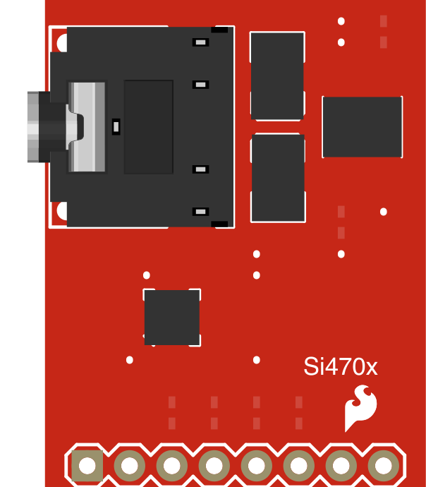
 Design with Digital FM Radio Receiver in Cirkit Designer
Introduction
The SparkFun Si4703 FM Tuner Evaluation Board is a compact and efficient digital FM radio receiver designed to receive frequency modulation (FM) radio signals and convert them into high-quality audio signals. This module leverages the Si4703 IC, a highly integrated FM tuner chip, to provide features such as digital tuning, RDS (Radio Data System) support, and stereo audio output. Its small form factor and ease of use make it ideal for hobbyists, students, and professionals working on audio and radio-related projects.
Explore Projects Built with Digital FM Radio Receiver
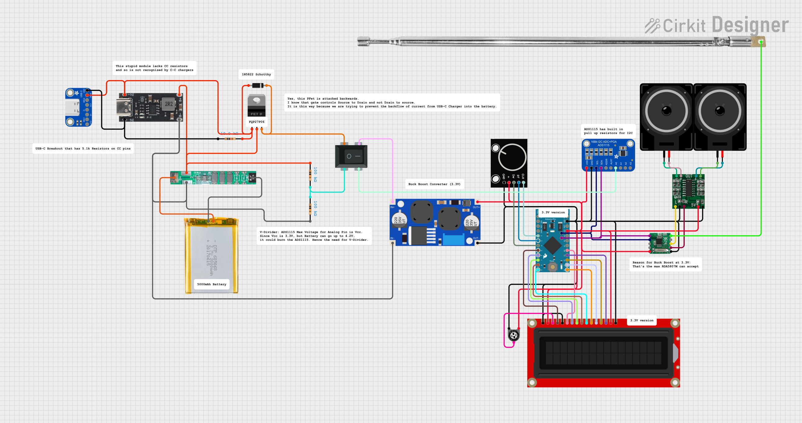 Open Project in Cirkit Designer
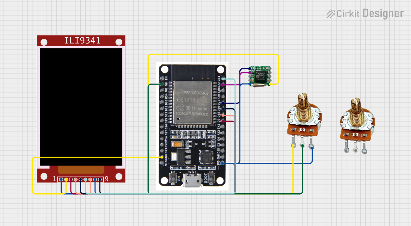 Open Project in Cirkit Designer
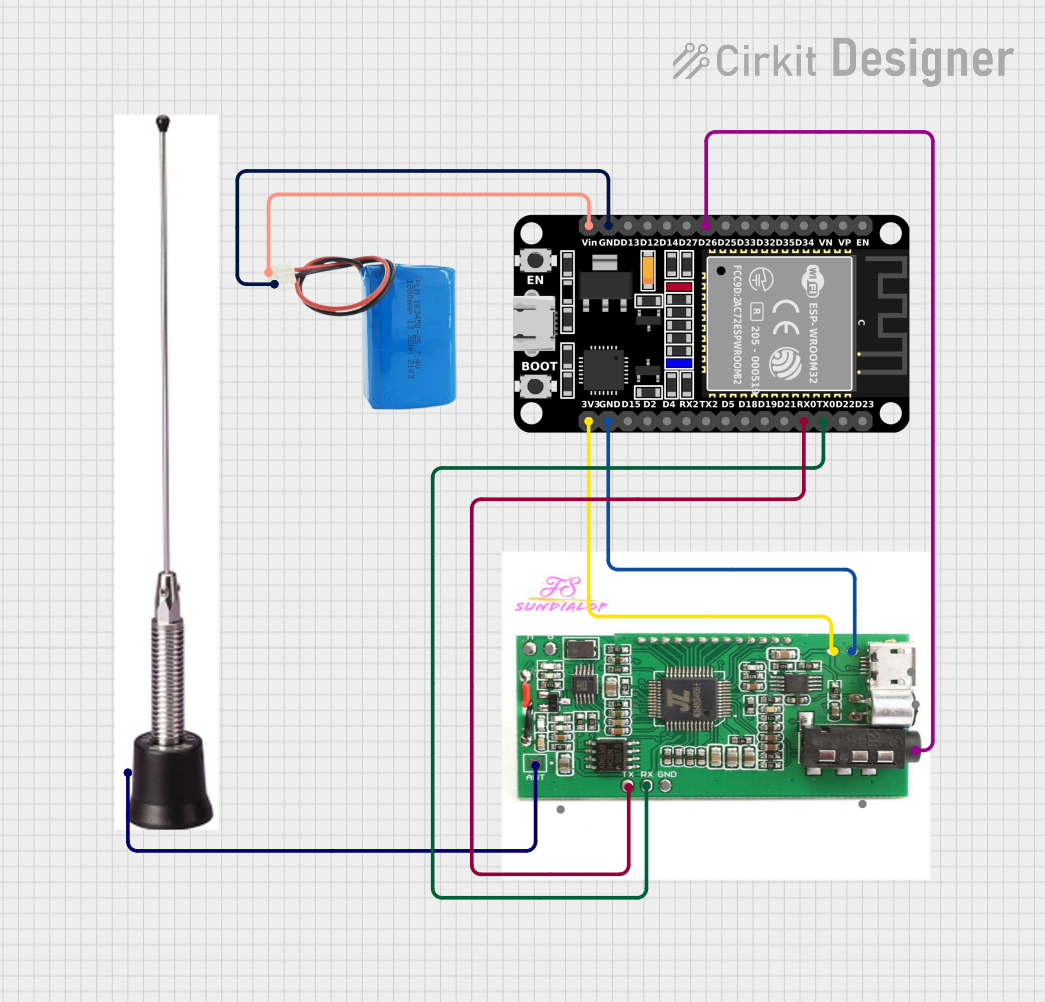 Open Project in Cirkit Designer
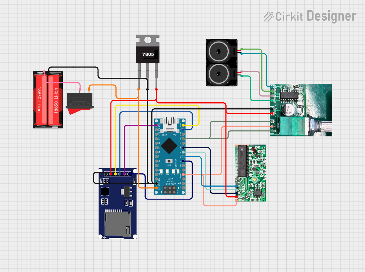 Open Project in Cirkit Designer
Explore Projects Built with Digital FM Radio Receiver
Open Project in Cirkit DesignerOpen Project in Cirkit DesignerOpen Project in Cirkit DesignerOpen Project in Cirkit DesignerCommon Applications and Use Cases
- Portable FM radio devices
- DIY audio systems and boomboxes
- Embedded systems requiring FM radio functionality
- Educational projects for learning about radio frequency (RF) communication
- Internet of Things (IoT) devices with FM radio integration
Technical Specifications
The following table outlines the key technical details of the Si4703 FM Tuner Evaluation Board:
| Parameter | Specification |
|---|---|
| Operating Voltage | 2.7V to 5.5V |
| Operating Current | ~20mA |
| Frequency Range | 76MHz to 108MHz |
| Audio Output | Stereo (Left and Right channels) |
| Communication Interface | I²C |
| RDS Support | Yes |
| Antenna Input | External antenna required (via pin) |
| Dimensions | 1.0" x 0.6" (25.4mm x 15.24mm) |
Pin Configuration and Descriptions
The Si4703 FM Tuner Evaluation Board has the following pinout:
| Pin Name | Pin Type | Description |
|---|---|---|
| GND | Power | Ground connection for the module |
| 3.3V | Power | 3.3V power supply input |
| SDA | I²C Data | Serial data line for I²C communication |
| SCL | I²C Clock | Serial clock line for I²C communication |
| RST | Input | Reset pin to initialize the module |
| ANT | Input | Antenna input for receiving FM signals |
| LOUT | Output | Left audio channel output |
| ROUT | Output | Right audio channel output |
Usage Instructions
How to Use the Component in a Circuit
- Power Supply: Connect the
3.3Vpin to a 3.3V power source and theGNDpin to ground. - Antenna: Attach an external antenna to the
ANTpin. A simple wire of appropriate length can serve as an antenna. - Audio Output: Connect the
LOUTandROUTpins to an audio amplifier or headphones for stereo audio output. - I²C Communication: Connect the
SDAandSCLpins to the corresponding I²C pins on your microcontroller (e.g., Arduino). - Reset: Use the
RSTpin to reset the module during initialization.
Important Considerations and Best Practices
- Antenna Selection: Use a properly tuned antenna for optimal FM signal reception. A 75cm wire works well for most FM frequencies.
- Power Supply: Ensure a stable 3.3V power supply to avoid noise and interference in the audio output.
- I²C Pull-Up Resistors: Add pull-up resistors (typically 4.7kΩ) to the
SDAandSCLlines if your microcontroller does not have internal pull-ups. - Audio Amplification: The audio output is line-level and may require amplification for driving speakers.
Example Code for Arduino UNO
Below is an example Arduino sketch to interface with the Si4703 FM Tuner Evaluation Board:
#include <Wire.h> // Include the Wire library for I²C communication

#define SI4703_ADDRESS 0x10 // I²C address of the Si4703 module

void setup() {
  Wire.begin(); // Initialize I²C communication
  Serial.begin(9600); // Initialize serial communication for debugging

  pinMode(2, OUTPUT); // Set pin 2 as output for the reset pin
  digitalWrite(2, LOW); // Hold the reset pin low
  delay(100); // Wait for 100ms
  digitalWrite(2, HIGH); // Release the reset pin
  delay(100); // Wait for the module to initialize

  Serial.println("Si4703 FM Tuner Initialized");
}

void loop() {
  // Example: Set the FM frequency to 101.1 MHz
  setFrequency(1011); // Frequency in 100kHz steps (e.g., 101.1 MHz = 1011)

  delay(1000); // Wait for 1 second
}

void setFrequency(int frequency) {
  Wire.beginTransmission(SI4703_ADDRESS); // Start I²C communication
  Wire.write(0x03); // Register address for channel tuning
  Wire.write((frequency >> 8) & 0xFF); // High byte of frequency
  Wire.write(frequency & 0xFF); // Low byte of frequency
  Wire.endTransmission(); // End I²C communication

  Serial.print("Tuned to frequency: ");
  Serial.println(frequency / 10.0, 1); // Print frequency in MHz
}
Troubleshooting and FAQs
Common Issues and Solutions
No Audio Output:
- Ensure the
LOUTandROUTpins are properly connected to an amplifier or headphones. - Verify that the module is powered correctly and the antenna is connected.
- Ensure the
Poor Signal Reception:
- Check the antenna connection and ensure it is of appropriate length.
- Move the module away from sources of interference, such as power supplies or other electronic devices.
I²C Communication Failure:
- Confirm the
SDAandSCLconnections to the microcontroller. - Add pull-up resistors to the I²C lines if necessary.
- Verify the I²C address (default is
0x10).
- Confirm the
Module Not Responding:
- Reset the module using the
RSTpin. - Ensure the power supply voltage is within the specified range (2.7V to 5.5V).
- Reset the module using the
FAQs
Q: Can I use this module with a 5V microcontroller?
A: Yes, but you must use level shifters for the I²C lines (SDA and SCL) to avoid damaging the module.
Q: Does the module support AM radio?
A: No, the Si4703 is designed specifically for FM radio reception.
Q: How do I enable RDS functionality?
A: RDS data can be accessed via specific registers in the Si4703. Refer to the Si4703 datasheet for detailed instructions.
Q: Can I use this module without an external antenna?
A: While it may work in areas with strong FM signals, an external antenna is recommended for optimal performance.