
How to Use Analog Discovery: Examples, Pinouts, and Specs
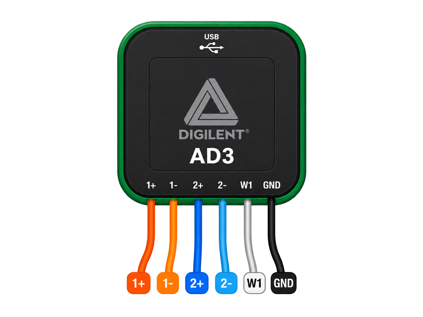
 Design with Analog Discovery in Cirkit Designer
Introduction
The Analog Discovery by Digilent (Manufacturer Part ID: 3) is a versatile USB-powered oscilloscope and signal generator designed for educational, prototyping, and experimental purposes. This compact device allows users to analyze and generate waveforms, measure signals, and perform a variety of electronic experiments. Its portability and wide range of features make it an essential tool for students, hobbyists, and professionals working on electronics projects.
Explore Projects Built with Analog Discovery
 Open Project in Cirkit Designer
 Open Project in Cirkit Designer
 Open Project in Cirkit Designer
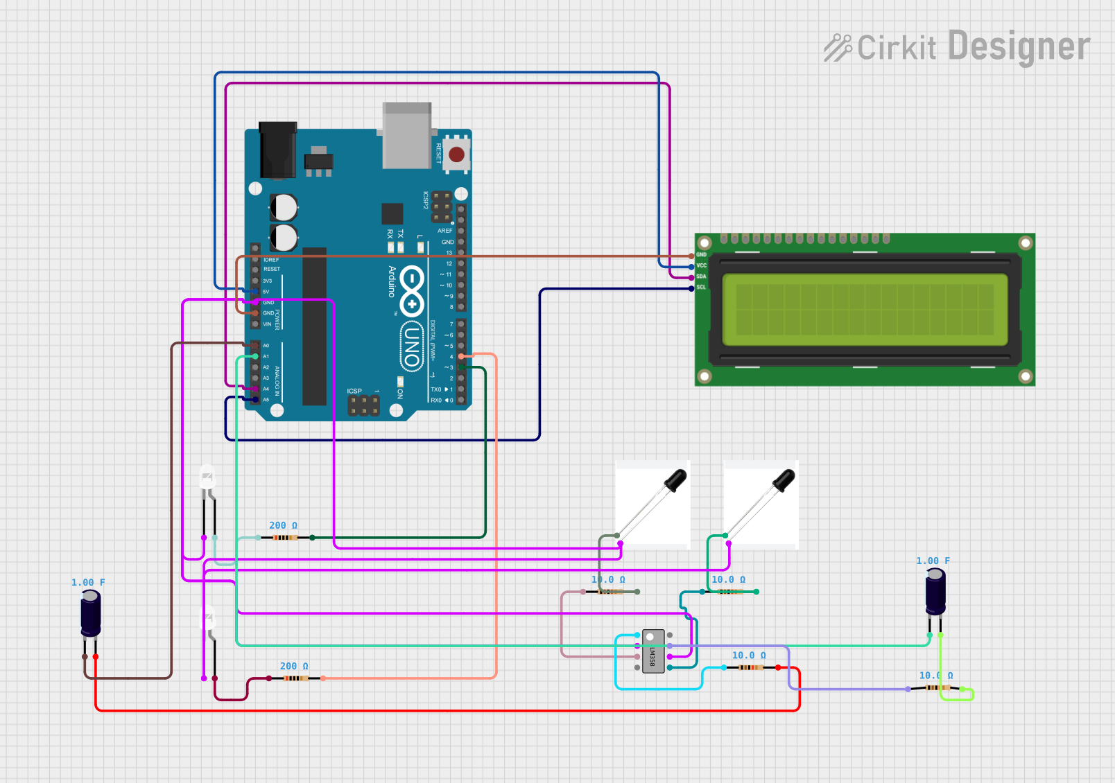 Open Project in Cirkit Designer
Explore Projects Built with Analog Discovery
Open Project in Cirkit DesignerOpen Project in Cirkit DesignerOpen Project in Cirkit DesignerOpen Project in Cirkit DesignerCommon Applications and Use Cases
- Signal analysis and waveform generation
- Circuit debugging and testing
- Educational demonstrations and laboratory experiments
- Prototyping and development of analog and digital circuits
- Frequency response analysis and Bode plotting
- Logic analysis and digital signal processing
Technical Specifications
The Analog Discovery is packed with features that make it a powerful tool for electronics enthusiasts. Below are its key technical specifications:
General Specifications
| Feature | Specification |
|---|---|
| Power Source | USB-powered (5V, 500mA typical) |
| Communication Interface | USB 2.0 |
| Dimensions | 3.23" x 3.23" x 0.89" (82mm x 82mm x 22.5mm) |
| Weight | 3.2 oz (90g) |
Oscilloscope Specifications
| Parameter | Specification |
|---|---|
| Channels | 2 (differential) |
| Bandwidth | 30 MHz |
| Sample Rate | 100 MS/s (single channel), 50 MS/s (dual channel) |
| Resolution | 14 bits |
| Input Range | ±25V |
| Input Impedance | 1MΩ |
Waveform Generator Specifications
| Parameter | Specification |
|---|---|
| Channels | 2 |
| Frequency Range | Up to 12 MHz |
| Amplitude Range | ±5V |
| Resolution | 14 bits |
Digital I/O and Logic Analyzer
| Parameter | Specification |
|---|---|
| Channels | 16 (3.3V logic, 5V tolerant) |
| Sample Rate | Up to 100 MS/s |
Pin Configuration and Descriptions
The Analog Discovery uses a 2x15 female header for its connections. Below is the pinout:
| Pin Number | Pin Name | Description |
|---|---|---|
| 1-2 | Oscilloscope 1 | Differential input for Channel 1 |
| 3-4 | Oscilloscope 2 | Differential input for Channel 2 |
| 5-6 | Waveform 1 | Output for Waveform Generator Channel 1 |
| 7-8 | Waveform 2 | Output for Waveform Generator Channel 2 |
| 9-24 | Digital I/O | 16 Digital I/O pins for logic analysis |
| 25-30 | GND | Ground connections |
Usage Instructions
How to Use the Analog Discovery in a Circuit
- Connect the Device: Plug the Analog Discovery into your computer using the provided USB cable.
- Install Software: Download and install the free WaveForms software from the Digilent website. This software is required to control the device.
- Connect Probes: Use the included flywire assembly to connect the oscilloscope, waveform generator, or digital I/O pins to your circuit.
- Configure Settings: Open the WaveForms software and configure the oscilloscope, waveform generator, or logic analyzer as needed for your application.
- Run Measurements: Start capturing signals, generating waveforms, or analyzing digital signals using the software interface.
Important Considerations and Best Practices
- Input Protection: Ensure that input signals do not exceed the ±25V range to avoid damaging the device.
- Grounding: Always connect the ground pin of the Analog Discovery to the ground of your circuit for accurate measurements.
- Signal Integrity: Use short, high-quality wires to minimize noise and signal degradation.
- Software Updates: Regularly update the WaveForms software to access the latest features and bug fixes.
Example: Using the Waveform Generator with Arduino UNO
The Analog Discovery can be used to generate a test signal for an Arduino UNO. Below is an example of Arduino code to read an analog signal generated by the Analog Discovery:
// Arduino UNO code to read an analog signal from the Analog Discovery
// Connect the waveform generator output to Arduino's A0 pin

const int analogPin = A0;  // Analog input pin
int sensorValue = 0;       // Variable to store the analog value

void setup() {
  Serial.begin(9600);  // Initialize serial communication at 9600 baud
}

void loop() {
  sensorValue = analogRead(analogPin);  // Read the analog input
  Serial.print("Analog Value: ");       // Print the value to the serial monitor
  Serial.println(sensorValue);
  delay(100);  // Delay for 100ms before the next reading
}
Troubleshooting and FAQs
Common Issues and Solutions
Device Not Recognized by Computer
- Ensure the USB cable is securely connected.
- Try a different USB port or cable.
- Install or update the WaveForms software and drivers.
No Signal Detected
- Verify that the probes are properly connected to the circuit.
- Check the configuration settings in the WaveForms software.
- Ensure the circuit is powered and functioning correctly.
Inaccurate Measurements
- Confirm that the ground pin is connected to the circuit ground.
- Use shorter wires to reduce noise and improve signal integrity.
- Calibrate the device using the WaveForms software.
FAQs
Q: Can the Analog Discovery be used with Raspberry Pi?
A: Yes, the Analog Discovery can be used with Raspberry Pi, but you will need to install the WaveForms software for Linux and ensure the Raspberry Pi has sufficient power to drive the device.
Q: Is the Analog Discovery compatible with macOS?
A: Yes, the WaveForms software is compatible with Windows, macOS, and Linux operating systems.
Q: Can I use the Analog Discovery to program microcontrollers?
A: While the Analog Discovery is not a programmer, it can be used to debug and analyze signals from microcontrollers.
Q: What is the maximum input voltage for the oscilloscope?
A: The maximum input voltage is ±25V. Exceeding this limit may damage the device.
Q: Does the Analog Discovery support Bode plotting?
A: Yes, the WaveForms software includes a Bode plotting tool for frequency response analysis.