How to Use Ohmmeter: Examples, Pinouts, and Specs
Introduction
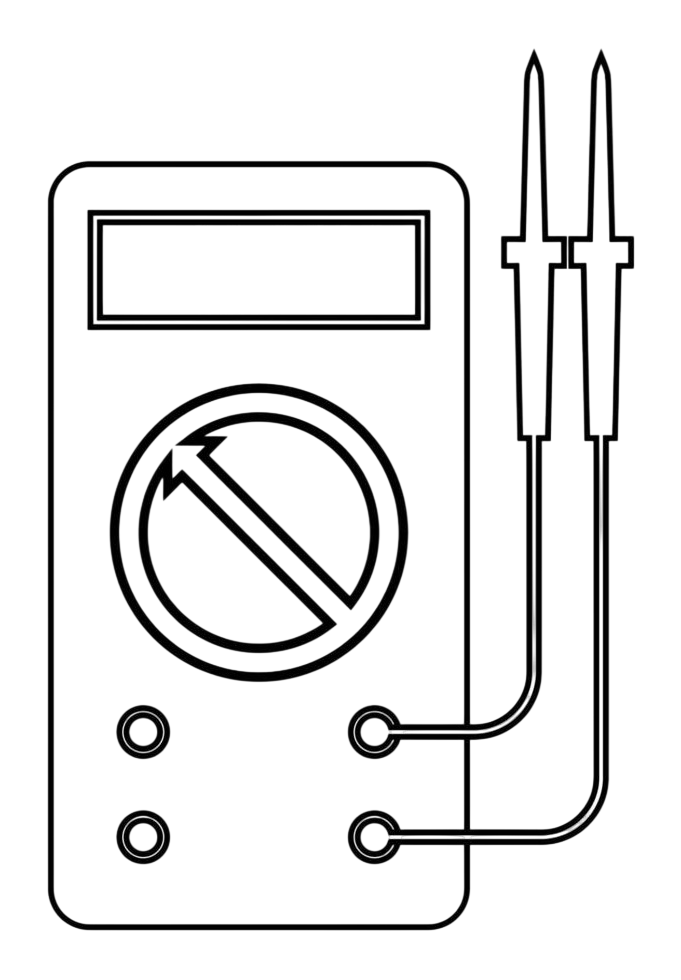
An Ohmmeter is an electrical instrument used to measure the resistance of a component or circuit in ohms (Ω). It is an essential tool for diagnosing electrical issues, as it helps determine whether a circuit is open, shorted, or functioning correctly. Ohmmeters are widely used in electronics, electrical engineering, and maintenance tasks to ensure proper circuit functionality and identify faults.
Explore Projects Built with Ohmmeter
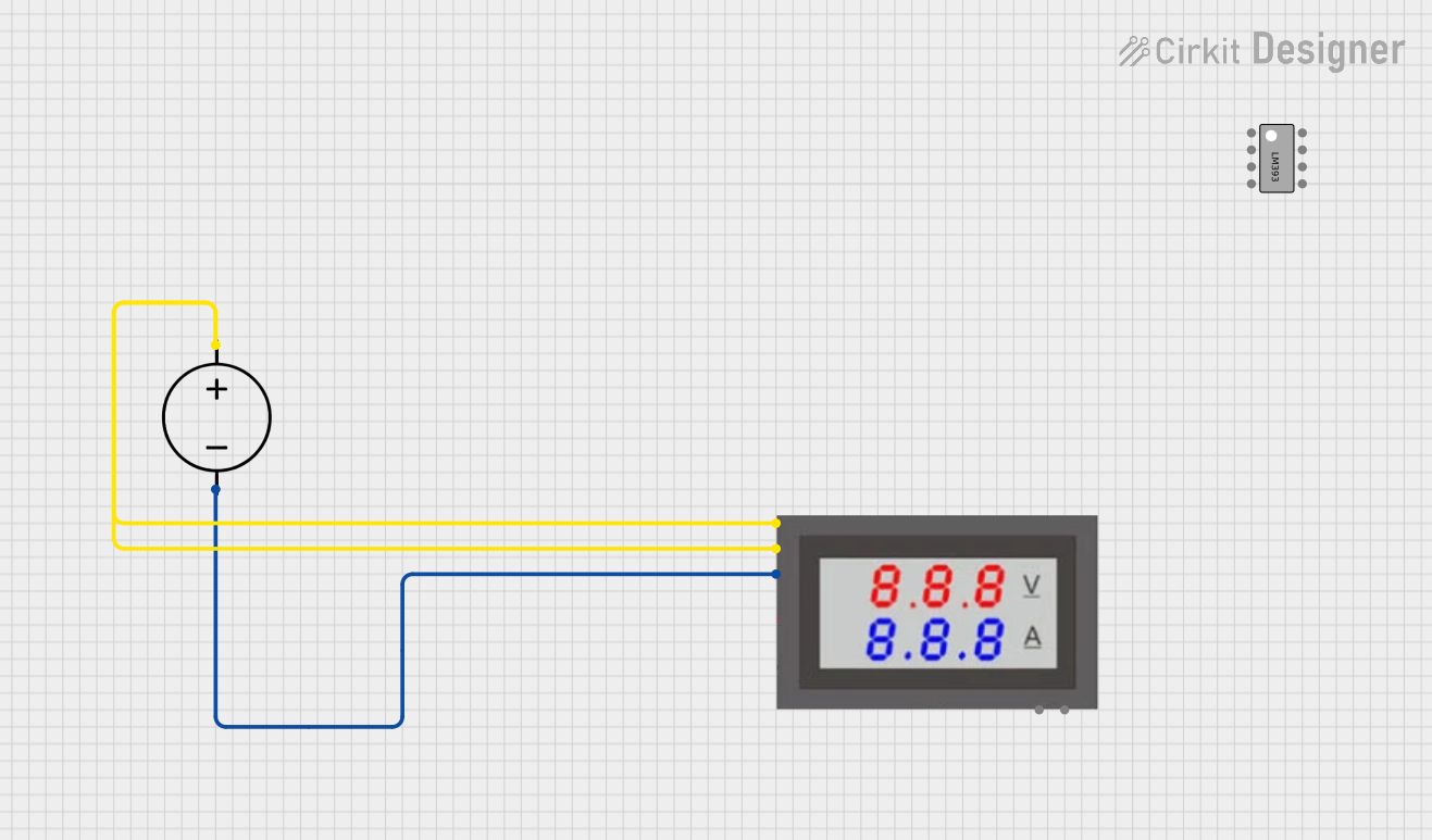
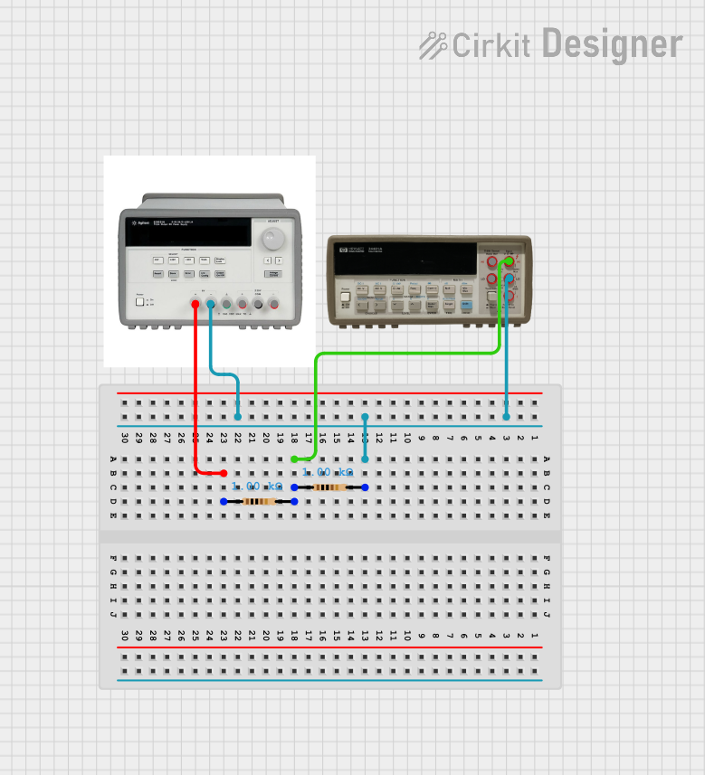
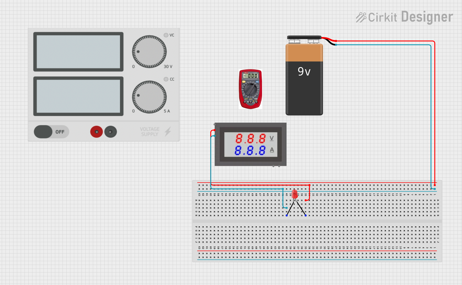
Explore Projects Built with Ohmmeter
Common Applications and Use Cases
- Measuring the resistance of resistors, wires, and other components.
- Diagnosing open or short circuits in electrical systems.
- Verifying the continuity of a circuit.
- Testing the condition of fuses, switches, and connectors.
- Troubleshooting and repairing electronic devices.
Technical Specifications
Ohmmeters come in various types, including analog and digital models. Below are the general technical specifications for a typical digital Ohmmeter:
| Specification | Details |
|---|---|
| Measurement Range | 0.1 Ω to 20 MΩ (varies by model) |
| Accuracy | ±(0.5% to 2%) of reading, depending on the range and model |
| Display Type | Digital LCD or LED display |
| Power Supply | Battery-operated (commonly 9V or AA batteries) |
| Input Protection | Overload protection to prevent damage from high voltage or current |
| Resolution | 0.01 Ω to 1 Ω, depending on the range |
| Test Voltage | Typically 1V to 5V (applied across the component being measured) |
| Operating Temperature | 0°C to 40°C |
| Dimensions | Compact handheld design (varies by manufacturer) |
Pin Configuration and Descriptions
Ohmmeters typically have two test leads (probes) for measurement. These leads are color-coded for easy identification:
| Pin/Lead | Description |
|---|---|
| Red Lead | Positive probe, connected to the circuit/component under test. |
| Black Lead | Negative probe, connected to the other end of the circuit/component under test. |
Usage Instructions
How to Use the Ohmmeter in a Circuit
- Power On the Ohmmeter: Ensure the Ohmmeter is powered on and set to the appropriate resistance range.
- Disconnect Power from the Circuit: Always ensure the circuit or component being tested is not connected to a power source. Testing a live circuit can damage the Ohmmeter or give inaccurate readings.
- Connect the Test Leads:
- Attach the red lead to one end of the component or circuit.
- Attach the black lead to the other end.
- Read the Display: Observe the resistance value displayed on the screen. A low resistance value indicates good continuity, while a very high or infinite resistance suggests an open circuit.
- Interpret the Results:
- Zero or near-zero resistance: Indicates a short circuit.
- Expected resistance value: Indicates the component is functioning correctly.
- Infinite resistance: Indicates an open circuit or broken connection.
Important Considerations and Best Practices
- Ensure Proper Range Selection: If the resistance is unknown, start with the highest range and gradually decrease until a stable reading is obtained.
- Avoid Measuring Live Circuits: Always disconnect power before using the Ohmmeter to prevent damage or injury.
- Check the Test Leads: Inspect the probes for damage or wear, as faulty leads can result in inaccurate readings.
- Calibrate the Ohmmeter: Periodically calibrate the device to maintain accuracy, especially for precision measurements.
- Avoid Excessive Force: Do not apply excessive pressure on the probes, as this can damage the component or the Ohmmeter.
Example: Using an Ohmmeter with an Arduino UNO
While an Ohmmeter is not directly connected to an Arduino UNO, it can be used to measure the resistance of components in circuits designed for Arduino projects. For example, you can use the Ohmmeter to verify the resistance of a pull-up resistor in an Arduino circuit.
// Example Arduino code to demonstrate the use of a pull-up resistor
// This code is unrelated to the Ohmmeter but shows where resistance measurement
// might be useful in verifying circuit components.

const int buttonPin = 2;  // Pin connected to the button
const int ledPin = 13;    // Pin connected to the onboard LED

void setup() {
  pinMode(buttonPin, INPUT_PULLUP); // Enable internal pull-up resistor
  pinMode(ledPin, OUTPUT);
}

void loop() {
  int buttonState = digitalRead(buttonPin); // Read the button state

  if (buttonState == LOW) { // Button pressed (LOW due to pull-up resistor)
    digitalWrite(ledPin, HIGH); // Turn on the LED
  } else {
    digitalWrite(ledPin, LOW);  // Turn off the LED
  }
}
In this example, you can use an Ohmmeter to verify the resistance of the pull-up resistor (internal or external) to ensure proper functionality.
Troubleshooting and FAQs
Common Issues Users Might Face
No Reading or Infinite Resistance Displayed:
- Cause: The circuit is open, or the component is damaged.
- Solution: Check the connections and ensure the component is not broken.
Fluctuating or Unstable Readings:
- Cause: Poor contact between the probes and the component.
- Solution: Ensure the probes are securely connected and clean the contact points.
Incorrect Resistance Value:
- Cause: Incorrect range selection or a faulty Ohmmeter.
- Solution: Select the correct range and verify the Ohmmeter's calibration.
Ohmmeter Does Not Power On:
- Cause: Dead batteries or internal damage.
- Solution: Replace the batteries or inspect the device for faults.
FAQs
Q: Can I use an Ohmmeter to measure resistance in a live circuit?
A: No, always disconnect the power supply before using an Ohmmeter. Measuring resistance in a live circuit can damage the device and result in inaccurate readings.
Q: How do I know if my Ohmmeter is calibrated?
A: Test the Ohmmeter with a known resistor value. If the reading matches the resistor's value within the specified accuracy, the Ohmmeter is calibrated.
Q: What should I do if the Ohmmeter shows zero resistance?
A: Zero resistance typically indicates a short circuit. Verify the circuit or component for faults.
Q: Can I measure the resistance of a capacitor with an Ohmmeter?
A: No, an Ohmmeter is not designed to measure capacitance. However, it can help identify if a capacitor is shorted or open by checking for continuity.
By following this documentation, users can effectively utilize an Ohmmeter for various applications and troubleshoot common issues with ease.