How to Use RJ Power Feed Thru (custom): Examples, Pinouts, and Specs
Introduction
The RJ Power Feed Thru is a specialized connector designed to combine power and data transmission through an RJ-style interface. Manufactured by custom PCB, this component simplifies wiring by enabling the delivery of both power and data over a single cable. It is particularly useful in applications where space-saving and efficient wiring are critical.
Explore Projects Built with RJ Power Feed Thru (custom)


Explore Projects Built with RJ Power Feed Thru (custom)
Common Applications and Use Cases
- Power-over-Ethernet (PoE) systems
- IoT devices requiring both power and data connectivity
- Networked security cameras
- Industrial automation systems
- Smart home devices
Technical Specifications
The following table outlines the key technical details of the RJ Power Feed Thru:
| Parameter | Value |
|---|---|
| Manufacturer | custom PCB |
| Part ID | RJ Power Feed Thru |
| Voltage Rating | 5V to 48V DC |
| Current Rating | Up to 2A |
| Data Transmission | Supports Ethernet (10/100 Mbps) |
| Connector Type | RJ45 |
| Operating Temperature | -40°C to 85°C |
| Insulation Resistance | ≥ 500 MΩ |
| Contact Resistance | ≤ 20 mΩ |
| Dimensions | 21mm x 15mm x 12mm |
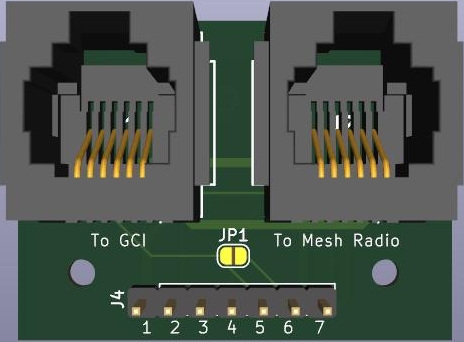
Pin Configuration and Descriptions
The RJ Power Feed Thru uses the standard RJ45 pinout with additional support for power delivery. Below is the pin configuration:
| Pin Number | Signal | Description |
|---|---|---|
| 1 | TX+ | Transmit Data Positive |
| 2 | TX- | Transmit Data Negative |
| 3 | RX+ | Receive Data Positive |
| 4 | V+ (Power) | Positive Power Supply |
| 5 | V+ (Power) | Positive Power Supply (redundant) |
| 6 | RX- | Receive Data Negative |
| 7 | GND (Power) | Ground |
| 8 | GND (Power) | Ground (redundant) |
Usage Instructions
How to Use the Component in a Circuit
- Wiring: Connect the RJ Power Feed Thru to an RJ45-compatible cable. Ensure that the cable supports both data and power transmission.
- Power Supply: Provide a DC power source within the voltage range of 5V to 48V. Connect the positive terminal to pins 4 and 5, and the ground terminal to pins 7 and 8.
- Data Connection: Use pins 1, 2, 3, and 6 for Ethernet data transmission. Ensure the connected device supports the required data rate (10/100 Mbps).
- Testing: Verify the connections using a multimeter to ensure proper voltage and continuity before powering the circuit.
Important Considerations and Best Practices
- Cable Selection: Use high-quality Ethernet cables (Cat5e or higher) to ensure reliable data and power transmission.
- Power Budget: Ensure the total power consumption of connected devices does not exceed the 2A current rating.
- Heat Management: If operating at higher currents, ensure adequate ventilation to prevent overheating.
- Polarity Check: Double-check the polarity of the power connections to avoid damage to the component or connected devices.
Example: Connecting to an Arduino UNO
The RJ Power Feed Thru can be used to power an Arduino UNO while simultaneously transmitting data. Below is an example setup:
- Connect the RJ Power Feed Thru to an Ethernet cable.
- Use a PoE injector to supply power and data through the cable.
- Connect the Arduino UNO's Ethernet shield to the RJ Power Feed Thru.
Here is an example Arduino sketch for basic Ethernet communication:
#include <SPI.h>
#include <Ethernet.h>

// MAC address and IP address for the Arduino
byte mac[] = { 0xDE, 0xAD, 0xBE, 0xEF, 0xFE, 0xED };
IPAddress ip(192, 168, 1, 177);

// Initialize the Ethernet server on port 80
EthernetServer server(80);

void setup() {
  // Start the Ethernet connection
  Ethernet.begin(mac, ip);

  // Start the server
  server.begin();
  Serial.begin(9600);
  Serial.println("Server is ready at IP: ");
  Serial.println(Ethernet.localIP());
}

void loop() {
  // Listen for incoming clients
  EthernetClient client = server.available();
  if (client) {
    Serial.println("New client connected");
    // Send a basic HTTP response
    client.println("HTTP/1.1 200 OK");
    client.println("Content-Type: text/html");
    client.println();
    client.println("<h1>Hello from Arduino!</h1>");
    client.stop();
  }
}
Troubleshooting and FAQs
Common Issues Users Might Face
No Power Delivery:
- Cause: Incorrect wiring or insufficient power supply.
- Solution: Verify the power source and ensure proper connections to pins 4, 5, 7, and 8.
Data Transmission Failure:
- Cause: Faulty Ethernet cable or incorrect pinout.
- Solution: Test the cable with a network cable tester and ensure the pinout matches the standard RJ45 configuration.
Overheating:
- Cause: Exceeding the current rating or poor ventilation.
- Solution: Reduce the load or improve airflow around the component.
Intermittent Connectivity:
- Cause: Loose connections or damaged contacts.
- Solution: Inspect the RJ45 connector for damage and ensure a secure fit.
Solutions and Tips for Troubleshooting
- Use a multimeter to check for continuity and proper voltage levels.
- Replace damaged cables or connectors to ensure reliable operation.
- If using PoE, ensure the injector or switch is compatible with the RJ Power Feed Thru's voltage and current ratings.
By following this documentation, users can effectively integrate the RJ Power Feed Thru into their projects, ensuring reliable power and data transmission.