How to Use SCHNEIDER: Examples, Pinouts, and Specs
Introduction
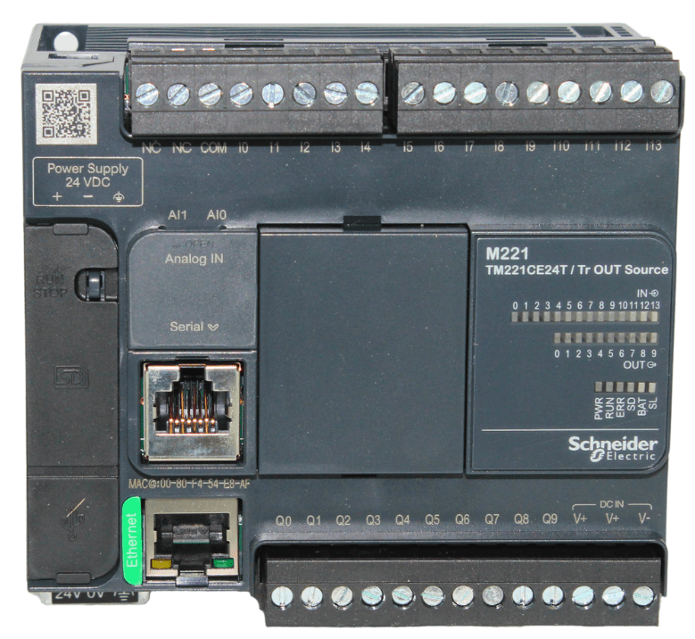
The TM221CE24T is a compact Programmable Logic Controller (PLC) manufactured by Schneider Electric, a global leader in energy management and automation solutions. This PLC is part of the Modicon M221 series, designed for small to medium-sized automation applications. It offers high performance, flexibility, and ease of use, making it an ideal choice for industrial control systems, machine automation, and process control.
Explore Projects Built with SCHNEIDER


Explore Projects Built with SCHNEIDER
Common Applications and Use Cases
- Industrial automation and control systems
- Machine automation for manufacturing
- Process control in industries such as food and beverage, packaging, and material handling
- Building automation for HVAC and lighting systems
- Energy management and monitoring
Technical Specifications
The TM221CE24T is a versatile PLC with the following key technical specifications:
General Specifications
| Parameter | Value |
|---|---|
| Manufacturer | Schneider Electric |
| Series | Modicon M221 |
| Part Number | TM221CE24T |
| Supply Voltage | 24 V DC |
| Digital Inputs | 14 |
| Digital Outputs | 10 (Transistor type) |
| Communication Ports | Ethernet, Serial (RS485) |
| Programming Environment | SoMachine Basic |
| Memory | 256 kB (Application Memory) |
| Operating Temperature Range | -10°C to +55°C |
| Dimensions (H x W x D) | 90 x 95 x 70 mm |
Pin Configuration and Descriptions
The TM221CE24T features multiple input and output terminals. Below is the pin configuration for its digital inputs and outputs:
Digital Inputs
| Pin Number | Description | Voltage Range |
|---|---|---|
| I0 - I13 | Digital Input Channels | 0 - 24 V DC |
Digital Outputs
| Pin Number | Description | Output Type | Max Current |
|---|---|---|---|
| Q0 - Q9 | Digital Output Channels | Transistor (PNP) | 0.5 A |
Communication Ports
| Port | Description | Protocols Supported |
|---|---|---|
| Ethernet | Ethernet Communication | Modbus TCP |
| Serial | RS485 Communication | Modbus RTU |
Usage Instructions
The TM221CE24T is designed for easy integration into automation systems. Follow these steps to use the component effectively:
Step 1: Power Supply Connection
- Connect a 24 V DC power supply to the PLC's power input terminals.
- Ensure the power supply is stable and within the specified voltage range.
Step 2: Wiring Digital Inputs and Outputs
- Connect sensors, switches, or other input devices to the digital input terminals (I0 - I13).
- Connect actuators, relays, or other output devices to the digital output terminals (Q0 - Q9).
- Use appropriate wiring and ensure proper insulation to avoid short circuits.
Step 3: Communication Setup
- For Ethernet communication, connect the PLC to a network using an Ethernet cable.
- For RS485 communication, connect the PLC to other devices using the serial port.
- Configure the communication settings (e.g., IP address, baud rate) in the SoMachine Basic software.
Step 4: Programming the PLC
- Install the SoMachine Basic software on your computer.
- Create a new project and select the TM221CE24T as the target device.
- Write the control logic using ladder diagrams or function block diagrams.
- Download the program to the PLC via Ethernet or USB.
Example Code for Modbus Communication with Arduino UNO
Below is an example of how to communicate with the TM221CE24T using an Arduino UNO via Modbus RTU:
#include <ModbusMaster.h>

// Instantiate ModbusMaster object
ModbusMaster node;

void setup() {
  Serial.begin(9600); // Initialize serial communication at 9600 baud
  node.begin(1, Serial); // Set Modbus slave ID to 1 and use Serial for communication
}

void loop() {
  uint8_t result;
  uint16_t data;

  // Read a holding register (e.g., register 40001)
  result = node.readHoldingRegisters(0x0000, 1);

  if (result == node.ku8MBSuccess) {
    data = node.getResponseBuffer(0); // Get the value of the register
    Serial.print("Register Value: ");
    Serial.println(data);
  } else {
    Serial.println("Failed to read register"); // Error handling
  }

  delay(1000); // Wait 1 second before the next read
}
Important Considerations and Best Practices
- Always follow the wiring diagram provided in the TM221CE24T user manual.
- Use proper grounding to minimize electrical noise and ensure reliable operation.
- Avoid exceeding the maximum current rating of the digital outputs to prevent damage.
- Regularly back up the PLC program to avoid data loss.
Troubleshooting and FAQs
Common Issues and Solutions
PLC Does Not Power On
- Check the power supply voltage and connections.
- Ensure the power supply meets the required specifications (24 V DC).
Inputs or Outputs Not Responding
- Verify the wiring of input and output devices.
- Check the program logic in the SoMachine Basic software.
Communication Failure
- Ensure the Ethernet or RS485 cables are properly connected.
- Verify the communication settings (e.g., IP address, baud rate).
PLC Program Not Running
- Check if the program is downloaded to the PLC.
- Ensure the PLC is in RUN mode.
FAQs
Q: Can the TM221CE24T be used with third-party HMIs?
A: Yes, the TM221CE24T supports Modbus TCP and Modbus RTU protocols, making it compatible with most third-party HMIs.
Q: What is the maximum cable length for RS485 communication?
A: The maximum cable length for RS485 communication is typically 1200 meters, depending on the cable quality and baud rate.
Q: Is the TM221CE24T suitable for harsh environments?
A: The TM221CE24T operates within a temperature range of -10°C to +55°C and is designed for industrial environments. However, additional protection may be required in extremely harsh conditions.
Q: Can I expand the I/O capacity of the TM221CE24T?
A: Yes, the TM221CE24T supports expansion modules to increase the number of inputs and outputs.
By following this documentation, users can effectively integrate and operate the TM221CE24T in their automation systems.