How to Use TTL OPTPCB-03: Examples, Pinouts, and Specs
Introduction
The TTL OPTPCB-03 is a high-performance optocoupler designed to provide electrical isolation between high-voltage and low-voltage circuits. It achieves this by using an optical interface to transmit signals, ensuring that the two circuits remain electrically isolated while still allowing data or control signals to pass through. The component features a transistor output, making it ideal for digital applications where signal isolation and noise reduction are critical.
Explore Projects Built with TTL OPTPCB-03
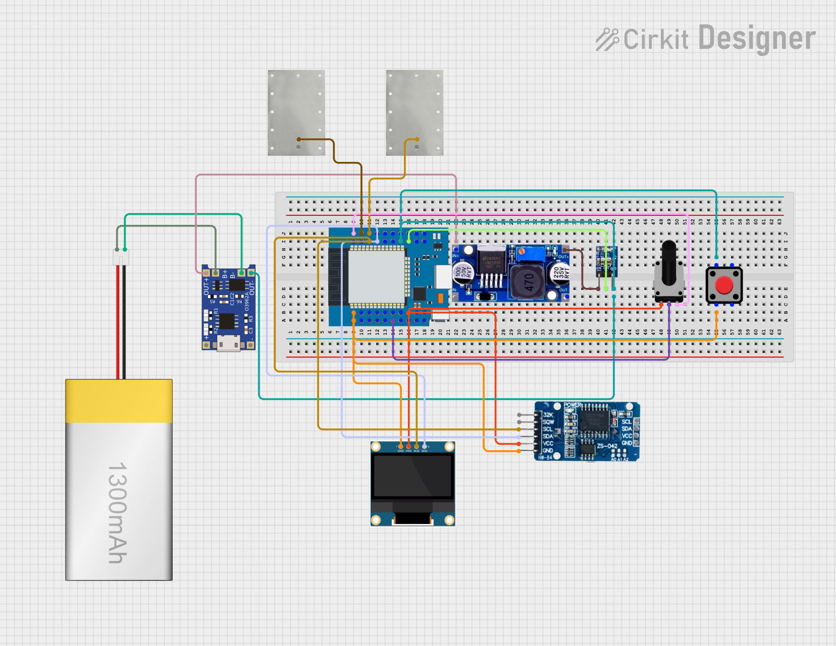


Explore Projects Built with TTL OPTPCB-03
Common Applications and Use Cases
- Signal isolation in microcontroller-based systems
- Noise reduction in industrial control systems
- Protection of sensitive low-voltage circuits from high-voltage transients
- Interfacing between different voltage domains in digital circuits
- Communication between high-power and low-power systems
Technical Specifications
Key Technical Details
| Parameter | Value |
|---|---|
| Input Voltage (LED) | 1.2V typical, 1.4V max |
| Forward Current (LED) | 10mA typical, 20mA max |
| Output Voltage (Transistor) | 5V max |
| Output Current (Transistor) | 50mA max |
| Isolation Voltage | 5000V RMS |
| Propagation Delay | 4µs typical |
| Operating Temperature | -40°C to +85°C |
| Package Type | PCB-mounted, 4-pin DIP |
Pin Configuration and Descriptions
| Pin Number | Name | Description |
|---|---|---|
| 1 | Anode (LED) | Positive terminal of the internal LED. |
| 2 | Cathode (LED) | Negative terminal of the internal LED. |
| 3 | Emitter | Emitter of the output transistor. |
| 4 | Collector | Collector of the output transistor. |
Usage Instructions
How to Use the TTL OPTPCB-03 in a Circuit
Connect the Input Side (LED):
- Connect the anode (Pin 1) to the positive side of the input signal through a current-limiting resistor.
- Connect the cathode (Pin 2) to the ground of the input circuit.
Connect the Output Side (Transistor):
- Connect the collector (Pin 4) to the positive voltage supply of the output circuit through a pull-up resistor.
- Connect the emitter (Pin 3) to the ground of the output circuit.
Choose a Suitable Resistor:
- Calculate the current-limiting resistor for the LED using the formula:
[
R = \frac{V_{in} - V_f}{I_f}
]
Where:
- (V_{in}) is the input voltage.
- (V_f) is the forward voltage of the LED (1.2V typical).
- (I_f) is the desired forward current (10mA typical).
- Calculate the current-limiting resistor for the LED using the formula:
[
R = \frac{V_{in} - V_f}{I_f}
]
Where:
Verify Isolation:
- Ensure that the input and output grounds are not connected to maintain electrical isolation.
Important Considerations and Best Practices
- Current Limiting: Always use a resistor to limit the current through the LED to prevent damage.
- Pull-Up Resistor: Use an appropriate pull-up resistor on the output side to ensure proper signal levels.
- Operating Conditions: Ensure the component operates within its specified voltage, current, and temperature limits.
- Signal Polarity: The input signal should be positive with respect to the cathode (Pin 2).
Example: Connecting to an Arduino UNO
The TTL OPTPCB-03 can be used to interface an Arduino UNO with a high-voltage circuit. Below is an example circuit and code:
Circuit Diagram
- Connect Pin 1 (Anode) to an Arduino digital pin (e.g., D3) through a 220Ω resistor.
- Connect Pin 2 (Cathode) to the Arduino ground (GND).
- Connect Pin 4 (Collector) to a 5V supply through a 10kΩ pull-up resistor.
- Connect Pin 3 (Emitter) to the ground of the output circuit.
Arduino Code
// Example code for using TTL OPTPCB-03 with Arduino UNO
const int inputPin = 3;  // Pin connected to the optocoupler's anode
const int outputPin = 7; // Pin connected to the optocoupler's output

void setup() {
  pinMode(inputPin, OUTPUT); // Set the input pin as output
  pinMode(outputPin, INPUT); // Set the output pin as input
}

void loop() {
  digitalWrite(inputPin, HIGH); // Turn on the LED inside the optocoupler
  delay(1000);                 // Wait for 1 second
  digitalWrite(inputPin, LOW);  // Turn off the LED
  delay(1000);                 // Wait for 1 second
}
Troubleshooting and FAQs
Common Issues and Solutions
No Output Signal:
- Cause: The LED current is too low.
- Solution: Check the current-limiting resistor value and ensure the LED receives sufficient current (10mA typical).
Output Signal is Weak or Noisy:
- Cause: The pull-up resistor value is too high.
- Solution: Use a lower-value pull-up resistor (e.g., 10kΩ).
Loss of Isolation:
- Cause: Input and output grounds are connected.
- Solution: Ensure the input and output grounds are electrically isolated.
Component Overheating:
- Cause: Exceeding the maximum current or voltage ratings.
- Solution: Verify that the circuit operates within the specified limits.
FAQs
Q: Can the TTL OPTPCB-03 be used for analog signals?
A: The TTL OPTPCB-03 is optimized for digital signals. While it can transmit simple analog signals, the performance may degrade due to its limited linearity.
Q: What is the maximum switching speed of the TTL OPTPCB-03?
A: The typical propagation delay is 4µs, making it suitable for signals up to approximately 250kHz.
Q: How do I calculate the pull-up resistor value?
A: The pull-up resistor value depends on the desired output current and voltage. A common value is 10kΩ for most digital applications.
Q: Can I use the TTL OPTPCB-03 with a 3.3V system?
A: Yes, the TTL OPTPCB-03 is compatible with 3.3V systems, but ensure the pull-up resistor and input current-limiting resistor are appropriately calculated.