How to Use OLED 128x64 I2C Monochrome Display VDD-GND (SIM TEST): Examples, Pinouts, and Specs
Introduction
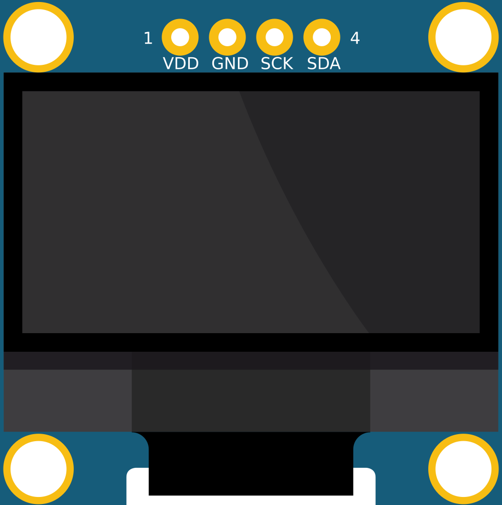
The OLED 128x64 I2C Monochrome Display is a compact and efficient display module that features a resolution of 128x64 pixels. Utilizing I2C communication, this display allows for easy integration with various microcontrollers, including popular platforms like Arduino. Its low power consumption makes it ideal for battery-operated devices and low-power applications. The display is well-suited for showing text, simple graphics, and user interfaces in embedded systems.
Explore Projects Built with OLED 128x64 I2C Monochrome Display VDD-GND (SIM TEST)
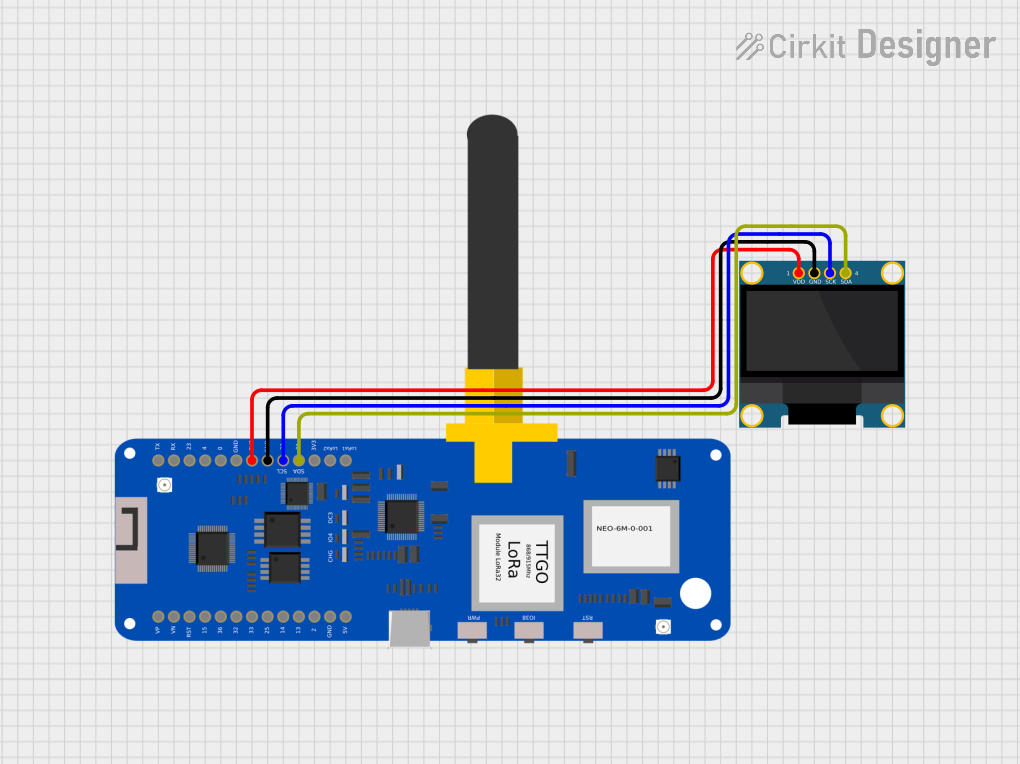

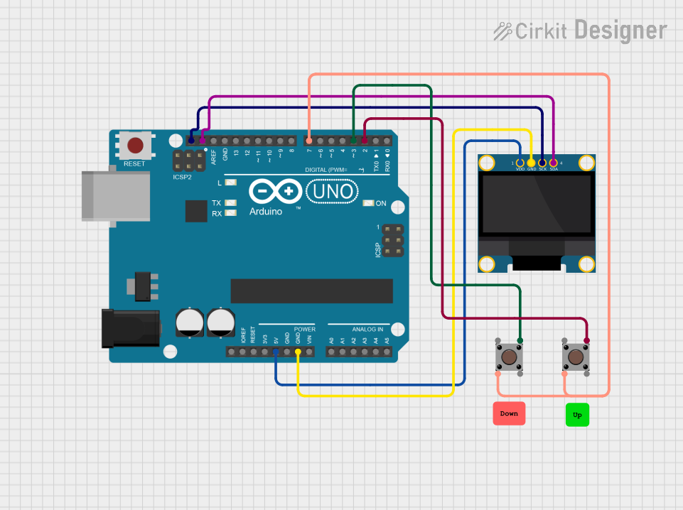

Explore Projects Built with OLED 128x64 I2C Monochrome Display VDD-GND (SIM TEST)
Common Applications and Use Cases
- Wearable Devices: Ideal for displaying health metrics and notifications.
- IoT Projects: Perfect for showing sensor data and status updates.
- Home Automation: Can be used in control panels to display system status.
- Educational Projects: Great for learning about displays and microcontroller interfacing.
Technical Specifications
Key Technical Details
| Specification | Value |
|---|---|
| Display Type | OLED |
| Resolution | 128 x 64 pixels |
| Interface | I2C |
| Operating Voltage | 3.3V - 5V |
| Current Consumption | ~20 mA (max) |
| Dimensions | 27.0 x 27.0 mm |
| Weight | ~10 g |
Pin Configuration and Descriptions
| Pin Name | Pin Number | Description |
|---|---|---|
| VDD | 1 | Power supply (3.3V - 5V) |
| GND | 2 | Ground connection |
| SCL | 3 | I2C Clock line |
| SDA | 4 | I2C Data line |
Usage Instructions
How to Use the Component in a Circuit
Wiring the Display:
- Connect the VDD pin to the power supply (3.3V or 5V).
- Connect the GND pin to the ground.
- Connect the SCL pin to the I2C clock pin of your microcontroller.
- Connect the SDA pin to the I2C data pin of your microcontroller.
Library Installation:
- For Arduino users, install the
Adafruit_SSD1306andAdafruit_GFXlibraries via the Library Manager.
- For Arduino users, install the
Sample Code: Below is a simple example code to initialize the OLED display and display "Hello, World!".
#include <Wire.h>
#include <Adafruit_GFX.h>
#include <Adafruit_SSD1306.h>

// Define display dimensions
#define SCREEN_WIDTH 128
#define SCREEN_HEIGHT 64

// Create display object
Adafruit_SSD1306 display(SCREEN_WIDTH, SCREEN_HEIGHT, &Wire, -1);

void setup() {
    // Initialize the display
    display.begin(SSD1306_I2C_ADDRESS, 0x3C);
    display.clearDisplay(); // Clear the buffer
    display.setTextSize(1); // Set text size
    display.setTextColor(SSD1306_WHITE); // Set text color
    display.setCursor(0, 0); // Set cursor position
    display.println("Hello, World!"); // Print text
    display.display(); // Display the buffer
}

void loop() {
    // Nothing to do here
}
Important Considerations and Best Practices
- Ensure that the power supply voltage is within the specified range (3.3V - 5V).
- Use pull-up resistors on the I2C lines if necessary, especially for longer connections.
- Avoid connecting the display to a power source while the microcontroller is powered off to prevent damage.
Troubleshooting and FAQs
Common Issues Users Might Face
Display Not Turning On:
- Check the power connections (VDD and GND).
- Ensure the I2C address is correct in the code (default is usually 0x3C).
Garbage Characters Displayed:
- Verify the I2C connections (SDA and SCL).
- Ensure that the correct libraries are installed and included in the code.
Flickering Display:
- Check for loose connections or interference from other components.
- Ensure that the display is properly initialized in the code.
Solutions and Tips for Troubleshooting
- Use an I2C scanner sketch to confirm the display's I2C address.
- Double-check the wiring against the pin configuration table.
- If using multiple I2C devices, ensure they have unique addresses.
By following this documentation, users can effectively integrate and utilize the OLED 128x64 I2C Monochrome Display in their projects, ensuring a smooth and successful experience.