How to Use CAN BUS: Examples, Pinouts, and Specs
Introduction
The Controller Area Network (CAN) bus is a robust and efficient communication protocol designed to enable seamless data exchange between microcontrollers and devices in real-time. Originally developed for automotive applications, the CAN bus has become a standard for various industries due to its reliability, fault tolerance, and ability to operate without a host computer. It is particularly well-suited for environments where multiple devices need to communicate efficiently and reliably.
Explore Projects Built with CAN BUS

Explore Projects Built with CAN BUS
Common Applications and Use Cases
- Automotive systems (e.g., engine control units, airbags, and infotainment systems)
- Industrial automation and robotics
- Medical devices and equipment
- Building automation (e.g., HVAC systems)
- Aerospace and marine systems
- IoT devices requiring real-time communication
Technical Specifications
The CAN bus operates based on a differential signaling method, ensuring high noise immunity and reliable communication. Below are the key technical specifications:
General Specifications
| Parameter | Value |
|---|---|
| Communication Speed | Up to 1 Mbps (Classical CAN) |
| Voltage Levels | 2.5V (dominant) and 0V (recessive) |
| Maximum Nodes | 120 devices per bus |
| Bus Length | Up to 40 meters at 1 Mbps |
| Protocol Standard | ISO 11898-1 and ISO 11898-2 |
Pin Configuration and Descriptions
The CAN bus typically uses a 2-wire differential signaling system. Below is the pin configuration for a standard CAN transceiver module:
| Pin Name | Description |
|---|---|
| CAN_H | High-level CAN signal (dominant state: 3.5V, recessive state: 2.5V) |
| CAN_L | Low-level CAN signal (dominant state: 1.5V, recessive state: 2.5V) |
| VCC | Power supply for the transceiver (typically 5V or 3.3V) |
| GND | Ground connection |
| RX | Receive data pin (connects to the microcontroller's RX pin) |
| TX | Transmit data pin (connects to the microcontroller's TX pin) |
Usage Instructions
How to Use the CAN Bus in a Circuit
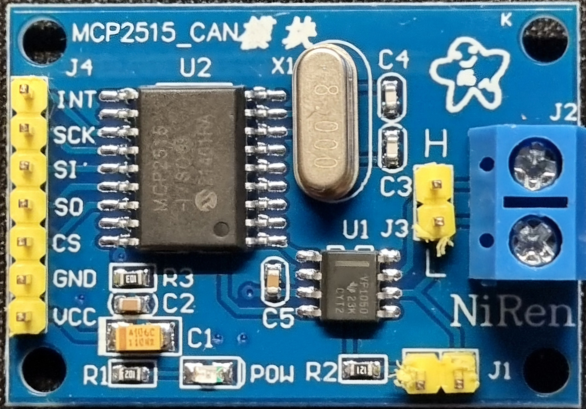
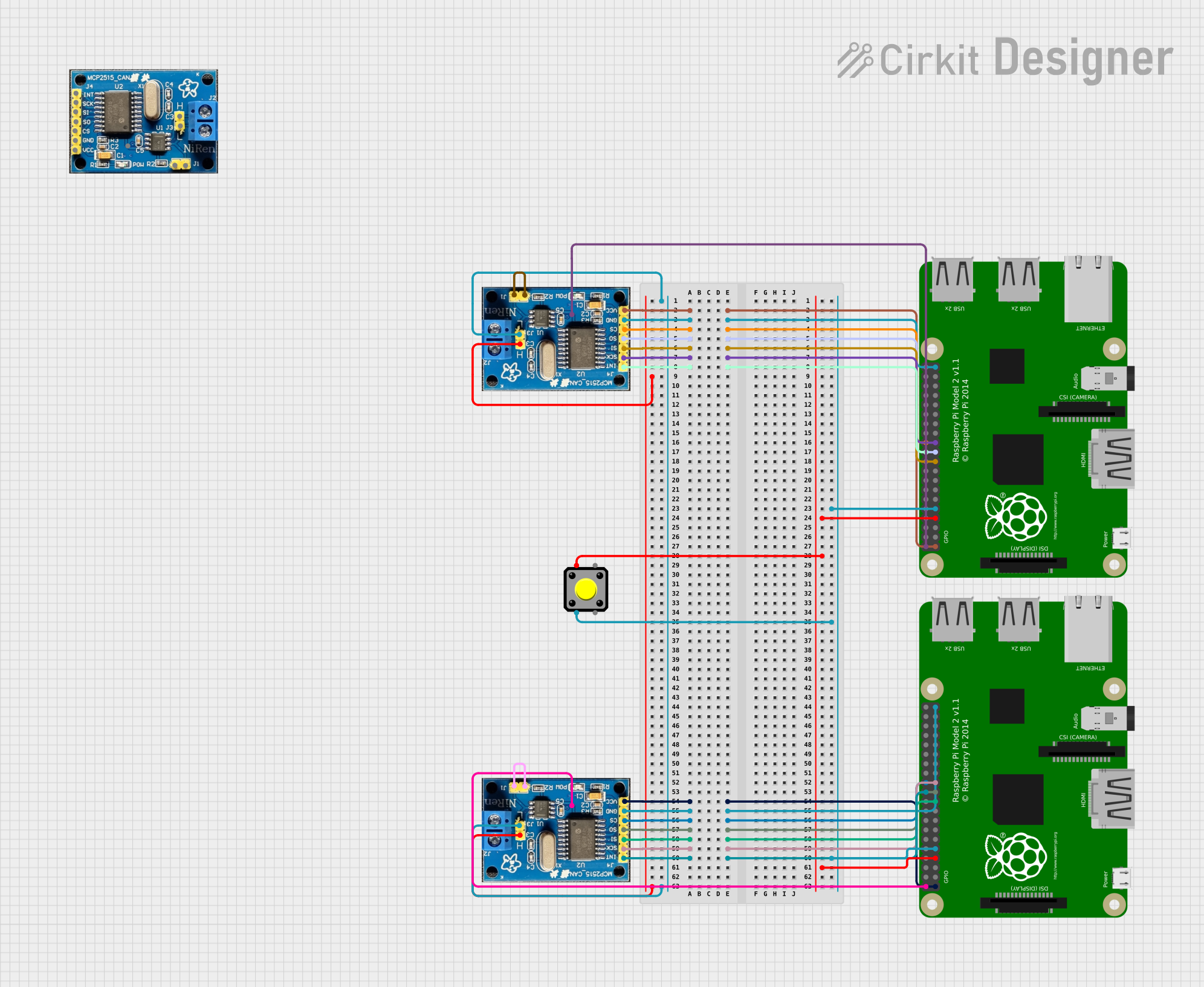
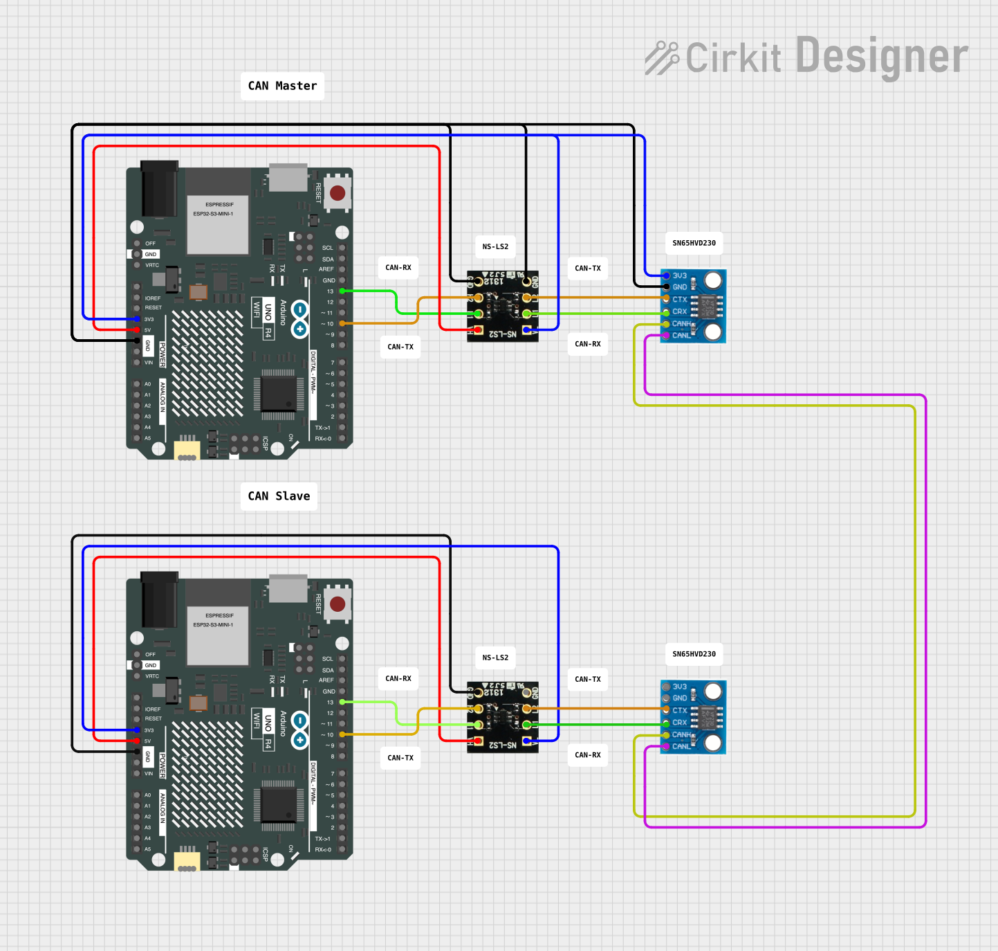
Connect the Transceiver Module: Use a CAN transceiver module (e.g., MCP2551 or SN65HVD230) to interface the CAN bus with your microcontroller.
- Connect
CAN_HandCAN_Lto the CAN bus lines. - Connect
VCCandGNDto the power supply. - Connect the
RXandTXpins to the corresponding UART pins on the microcontroller.
- Connect
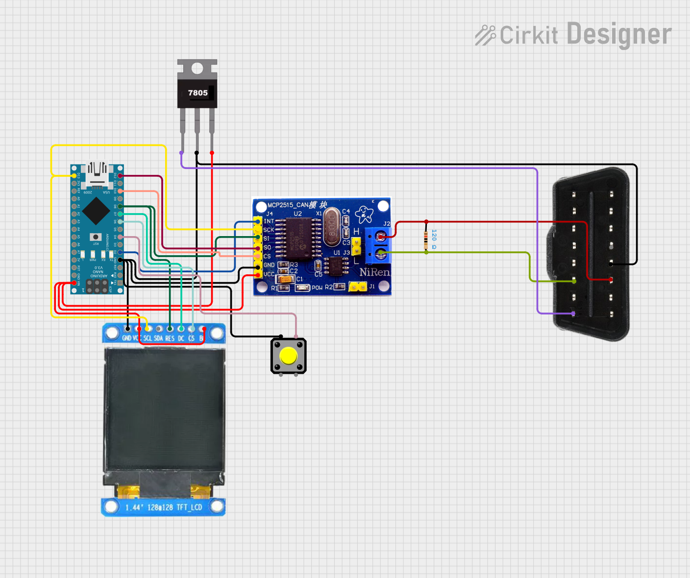
Add Termination Resistors: Place 120-ohm resistors at both ends of the CAN bus to prevent signal reflections.
Configure the Microcontroller:
- Set the baud rate to match the CAN bus speed (e.g., 500 kbps).
- Initialize the CAN controller with the appropriate settings (e.g., filters and masks).
Write and Read Data:
- Use the microcontroller's CAN library or API to send and receive messages.
- Messages are typically sent in frames, which include an identifier, data length, and payload.
Important Considerations and Best Practices
- Ensure all devices on the CAN bus operate at the same baud rate.
- Use twisted-pair cables for
CAN_HandCAN_Lto minimize electromagnetic interference (EMI). - Avoid long stubs (branch connections) to maintain signal integrity.
- Verify that the total bus length and number of nodes comply with the CAN standard.
Example: Using CAN Bus with Arduino UNO
Below is an example of how to use the CAN bus with an Arduino UNO and an MCP2515 CAN module:
#include <SPI.h>
#include <mcp_can.h>

// Define the SPI CS pin for the MCP2515 module
#define CAN_CS_PIN 10

// Initialize the MCP_CAN object
MCP_CAN CAN(CAN_CS_PIN);

void setup() {
  Serial.begin(115200); // Start serial communication for debugging
  while (!Serial);

  // Initialize the CAN bus at 500 kbps
  if (CAN.begin(MCP_ANY, 500000, MCP_8MHZ) == CAN_OK) {
    Serial.println("CAN bus initialized successfully!");
  } else {
    Serial.println("Error initializing CAN bus.");
    while (1);
  }

  // Set the CAN bus to normal mode
  CAN.setMode(MCP_NORMAL);
  Serial.println("CAN bus set to normal mode.");
}

void loop() {
  // Example: Sending a CAN message
  byte data[8] = {0x01, 0x02, 0x03, 0x04, 0x05, 0x06, 0x07, 0x08};
  if (CAN.sendMsgBuf(0x100, 0, 8, data) == CAN_OK) {
    Serial.println("Message sent successfully!");
  } else {
    Serial.println("Error sending message.");
  }

  delay(1000); // Wait 1 second before sending the next message
}
Troubleshooting and FAQs
Common Issues and Solutions
No Communication on the CAN Bus:
- Cause: Incorrect baud rate or wiring.
- Solution: Verify that all devices are configured with the same baud rate and check the wiring.
Bus Errors or Data Corruption:
- Cause: Missing or incorrect termination resistors.
- Solution: Ensure 120-ohm resistors are placed at both ends of the CAN bus.
Intermittent Communication Failures:
- Cause: Excessive bus length or poor cable quality.
- Solution: Use shorter cables and twisted-pair wires for
CAN_HandCAN_L.
Microcontroller Not Receiving Data:
- Cause: Incorrect RX/TX pin connections.
- Solution: Double-check the connections between the transceiver and the microcontroller.
FAQs
Q: Can I use the CAN bus for non-automotive applications?
A: Yes, the CAN bus is widely used in industrial automation, medical devices, and other fields requiring reliable communication.
Q: What is the maximum data payload for a CAN message?
A: The maximum payload for a Classical CAN message is 8 bytes. For CAN FD (Flexible Data-rate), it can be up to 64 bytes.
Q: Do I need a specific library to use the CAN bus with Arduino?
A: Yes, libraries like mcp_can are commonly used to interface with MCP2515-based CAN modules.
Q: Can I connect devices with different voltage levels on the same CAN bus?
A: Yes, but you will need level shifters or transceivers that support the voltage levels of all devices.