How to Use Emergency Alarm: Examples, Pinouts, and Specs
Introduction
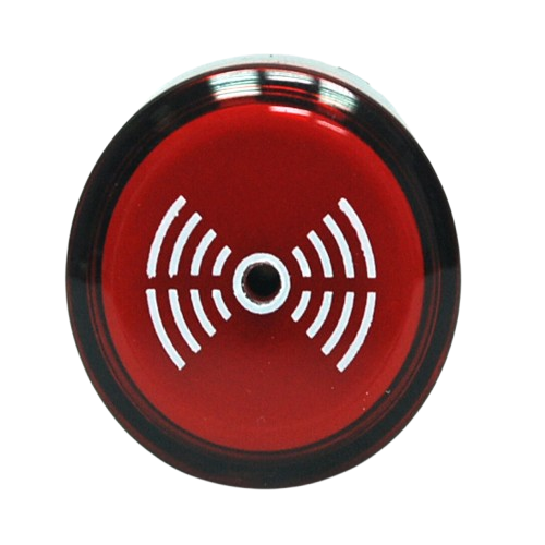
An Emergency Alarm is a device designed to alert individuals to an emergency situation, typically through sound, light, or both. It is a critical component in safety systems, ensuring timely warnings to prompt immediate action or evacuation. Emergency alarms are widely used in residential, commercial, and industrial settings, as well as in vehicles and public spaces.
Explore Projects Built with Emergency Alarm
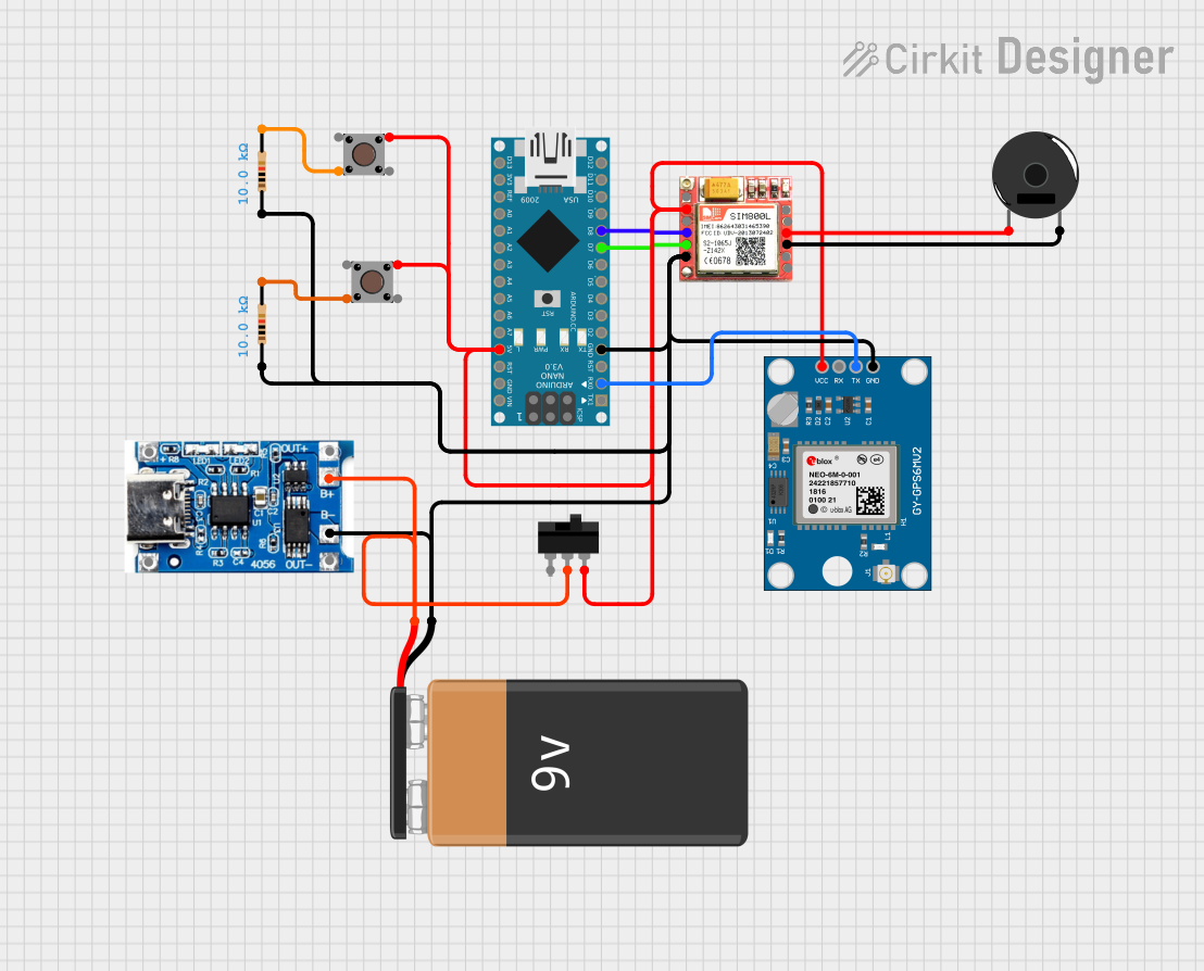
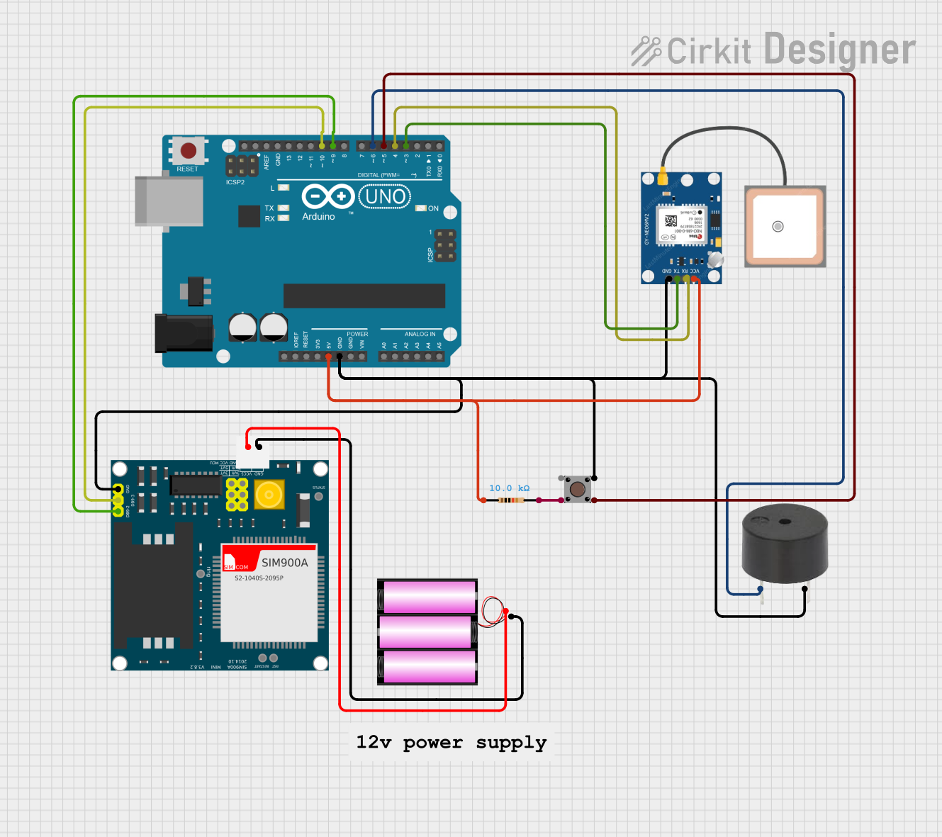

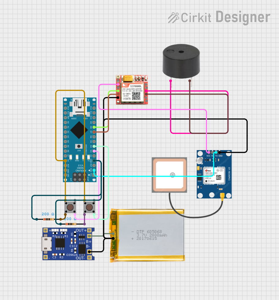
Explore Projects Built with Emergency Alarm
Common Applications and Use Cases
- Fire alarm systems in buildings
- Security systems for intrusion detection
- Industrial machinery fault alerts
- Emergency evacuation systems
- Medical alert systems for patients
- Vehicle alarms for collision or theft warnings
Technical Specifications
Key Technical Details
| Parameter | Value/Range |
|---|---|
| Operating Voltage | 5V to 24V DC (varies by model) |
| Current Consumption | 50mA to 200mA |
| Sound Output Level | 85dB to 120dB at 1 meter |
| Light Output (if applicable) | LED or strobe light, 1W to 5W |
| Operating Temperature | -20°C to 60°C |
| Dimensions | Varies by model (e.g., 50mm x 50mm x 30mm) |
| Mounting Type | Wall-mounted or panel-mounted |
Pin Configuration and Descriptions
| Pin Name | Description |
|---|---|
| VCC | Power supply input (5V to 24V DC) |
| GND | Ground connection |
| TRIG | Trigger input to activate the alarm (logic HIGH) |
| OUT (optional) | Output signal for external devices (e.g., relay) |
Usage Instructions
How to Use the Component in a Circuit
- Power Supply: Connect the
VCCpin to a DC power source (5V to 24V, depending on the model) and theGNDpin to the ground. - Triggering the Alarm: Use the
TRIGpin to activate the alarm. Apply a logic HIGH signal (e.g., 3.3V or 5V) to this pin to turn on the alarm. - Optional Output: If the alarm has an
OUTpin, it can be used to control external devices, such as a relay or another alarm.
Important Considerations and Best Practices
- Voltage Compatibility: Ensure the power supply voltage matches the alarm's operating voltage range.
- Current Rating: Verify that the power source can supply sufficient current for the alarm.
- Trigger Signal: Use a microcontroller, such as an Arduino, or a manual switch to provide the trigger signal.
- Mounting: Install the alarm in a location where it is clearly audible and/or visible.
- Environmental Conditions: Avoid exposing the alarm to extreme temperatures or moisture unless it is rated for such conditions.
Example: Connecting to an Arduino UNO
Below is an example of how to connect and control an emergency alarm using an Arduino UNO:
Circuit Diagram
- Connect the
VCCpin of the alarm to the 5V pin on the Arduino. - Connect the
GNDpin of the alarm to the GND pin on the Arduino. - Connect the
TRIGpin of the alarm to digital pin 8 on the Arduino.
Arduino Code
// Emergency Alarm Control with Arduino UNO
// This code triggers the alarm for 5 seconds when a button is pressed.

const int alarmPin = 8;  // Pin connected to the TRIG pin of the alarm
const int buttonPin = 7; // Pin connected to a push button

void setup() {
  pinMode(alarmPin, OUTPUT);  // Set alarm pin as output
  pinMode(buttonPin, INPUT_PULLUP); // Set button pin as input with pull-up
}

void loop() {
  // Check if the button is pressed
  if (digitalRead(buttonPin) == LOW) {
    digitalWrite(alarmPin, HIGH); // Activate the alarm
    delay(5000);                  // Keep the alarm on for 5 seconds
    digitalWrite(alarmPin, LOW);  // Deactivate the alarm
  }
}
Troubleshooting and FAQs
Common Issues and Solutions
| Issue | Possible Cause | Solution |
|---|---|---|
| Alarm does not activate | Incorrect wiring or loose connections | Verify all connections and wiring. |
| Alarm is too quiet | Insufficient power supply | Use a power source with adequate voltage and current. |
| Alarm triggers unexpectedly | Electrical noise or interference | Add a pull-down resistor to the TRIG pin. |
| Alarm does not turn off | Faulty trigger signal | Check the microcontroller or switch. |
FAQs
Can I use the alarm with a 12V power supply?
- Yes, if the alarm's operating voltage range includes 12V. Check the specifications.
Can I control multiple alarms with one Arduino?
- Yes, connect each alarm's
TRIGpin to a separate digital pin on the Arduino.
- Yes, connect each alarm's
What should I do if the alarm overheats?
- Ensure the alarm is not operating beyond its rated voltage or current. Improve ventilation if necessary.
Can I use the alarm outdoors?
- Only if it is rated for outdoor use. Otherwise, protect it from moisture and extreme temperatures.
This documentation provides a comprehensive guide to understanding, using, and troubleshooting an emergency alarm. Follow the instructions and best practices to ensure reliable operation in your safety systems.