How to Use Adafruit BNO085 9-DOF Orientation IMU Fusion: Examples, Pinouts, and Specs
Introduction
The Adafruit BNO085 9-DOF Orientation IMU Fusion is a sophisticated sensor module that integrates three key sensors: an accelerometer, a gyroscope, and a magnetometer. This combination allows for precise tracking of orientation and motion. The BNO085 uses advanced sensor fusion algorithms to deliver highly accurate measurements, making it ideal for applications in robotics, navigation, human-machine interface, and augmented reality.
Explore Projects Built with Adafruit BNO085 9-DOF Orientation IMU Fusion

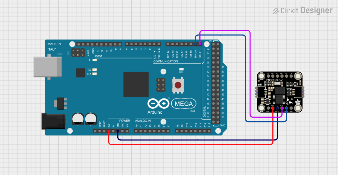
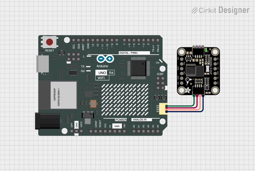
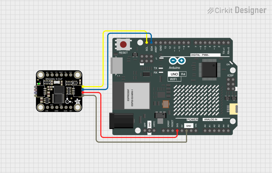
Explore Projects Built with Adafruit BNO085 9-DOF Orientation IMU Fusion
Common Applications and Use Cases
- Virtual and augmented reality devices
- Motion tracking and gesture detection
- Robotics and drone stabilization
- Navigation systems (e.g., compass and dead reckoning)
- Fitness and health monitoring devices
Technical Specifications
Key Technical Details
- Voltage Supply: 1.65V to 3.6V
- Current Consumption: 14 mA (typical use)
- Operating Temperature Range: -40°C to +85°C
- Output Data Rates: Up to 200 Hz
- Communication Interface: I2C (up to 400 kHz) and SPI (up to 3 MHz)
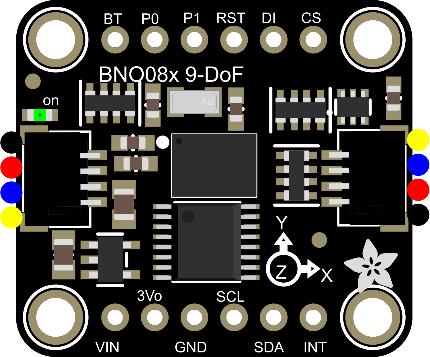
Pin Configuration and Descriptions
| Pin Number | Name | Description |
|---|---|---|
| 1 | VIN | Supply voltage (1.65V to 3.6V) |
| 2 | GND | Ground |
| 3 | SCL | I2C clock line / SPI clock line |
| 4 | SDA | I2C data line / SPI data line (MOSI) |
| 5 | SDO | SPI data line (MISO) |
| 6 | CS | SPI chip select (active low) |
| 7 | INT | Interrupt output (active low) |
| 8 | RST | Reset input (active low) |
Usage Instructions
How to Use the Component in a Circuit
- Power Supply: Connect the VIN pin to a 1.65V to 3.6V source and GND to the ground.
- Communication: Choose between I2C or SPI for communication with a microcontroller like the Arduino UNO.
- For I2C, connect SCL to the I2C clock and SDA to the I2C data.
- For SPI, connect SCL to SCK, SDA to MOSI, SDO to MISO, and CS to a digital pin for chip select.
- Interrupts (Optional): Connect the INT pin to a digital pin on the microcontroller if you wish to use interrupt-driven data acquisition.
- Reset (Optional): Connect the RST pin to a digital pin on the microcontroller if you need to manually reset the sensor.
Important Considerations and Best Practices
- Ensure that the power supply is within the specified voltage range to prevent damage.
- Use pull-up resistors on the I2C lines if they are not included in your microcontroller board.
- For SPI communication, ensure that the CS pin is set to HIGH before starting communication and pulled LOW during communication.
- Place the sensor away from magnetic fields and metals that can distort the magnetometer readings.
- Calibrate the sensor for accurate readings, following the manufacturer's guidelines.
Example Code for Arduino UNO
#include <Wire.h>
#include <Adafruit_BNO08x.h>

Adafruit_BNO08x bno08x = Adafruit_BNO08x();

void setup() {
  Serial.begin(115200);
  if (!bno08x.begin_I2C()) { // Start the sensor using I2C
    Serial.println("Failed to find BNO08x chip");
    while (1) { delay(10); }
  }
  Serial.println("BNO08x Found!");
}

void loop() {
  // Read the sensor
  if (bno08x.getEvent()) {
    Serial.print("Orientation: ");
    Serial.print(bno08x.roll);
    Serial.print(" Pitch: ");
    Serial.print(bno08x.pitch);
    Serial.print(" Yaw: ");
    Serial.println(bno08x.yaw);
  }
  delay(100);
}
Troubleshooting and FAQs
Common Issues Users Might Face
- Sensor Not Detected: Ensure that the wiring is correct and the power supply is within the specified range.
- Inaccurate Readings: Calibrate the sensor and make sure it's placed in an environment free from magnetic interference.
- Communication Errors: Check the pull-up resistors on I2C lines or the CS line handling for SPI.
Solutions and Tips for Troubleshooting
- Double-check connections and solder joints for any loose connections or shorts.
- Use the
Wirelibrary'ssetClock()function to adjust the I2C clock speed if necessary. - For SPI, ensure that other SPI devices on the same bus are not interfering with the communication.
FAQs
Q: Can the BNO085 run on 5V systems like the Arduino UNO? A: The BNO085 requires a voltage between 1.65V and 3.6V. Use a level shifter or voltage regulator when interfacing with 5V systems.
Q: How do I calibrate the BNO085? A: Follow the calibration procedure outlined in the datasheet, which typically involves moving the sensor through various orientations.
Q: What is the difference between BNO085 and its predecessors like BNO055? A: The BNO085 offers improved sensor fusion algorithms and a higher output data rate, among other enhancements.
Remember to refer to the official Adafruit BNO085 datasheet and the Adafruit Sensor Calibration guide for more detailed information.