The MS5611-01BA03 GY-63 is a high-resolution barometric pressure sensor module designed for precise atmospheric pressure and temperature measurements. It integrates the MS5611-01BA03 sensor with additional circuitry to simplify interfacing with microcontrollers. The module is widely used in applications such as:
Weather monitoring systems
Altitude measurement for aviation and hiking devices
Drone navigation and control
Environmental data logging
The GY-63 module provides I²C and SPI communication interfaces, making it versatile and easy to integrate into various projects.
Explore Projects Built with MS5611-01BA03 GY-63 Atmospheric Pressure Sensor Module [Bill Ludwig]
Use Cirkit Designer to design, explore, and prototype these projects online. Some projects support real-time simulation. Click "Open Project" to start designing instantly!
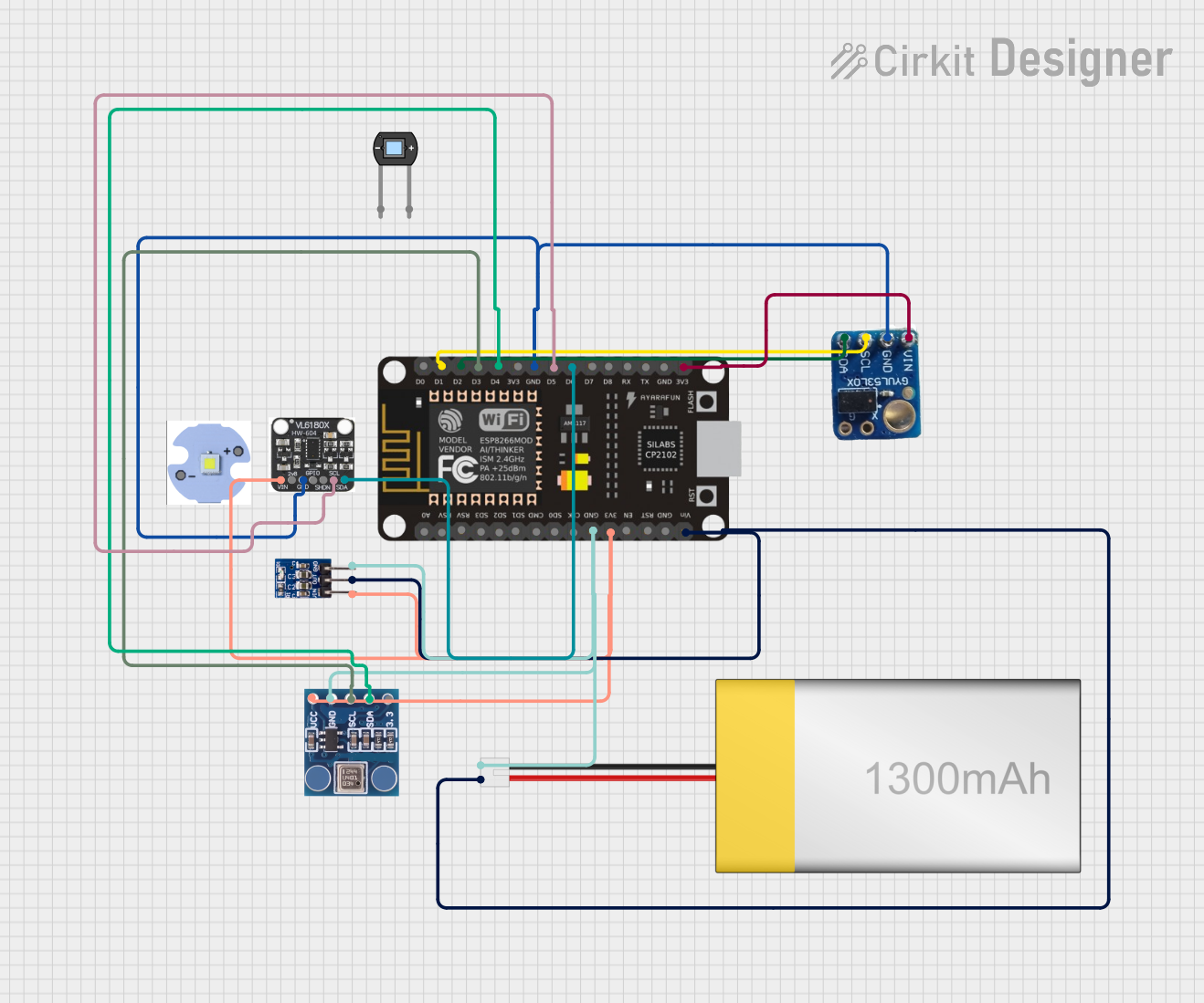
This circuit is designed around an ESP8266 NodeMCU microcontroller, which interfaces with a BMP180 barometric pressure sensor, a VL53L0X time-of-flight distance sensor, and a VL6180X proximity and ambient light sensor. The microcontroller collects environmental data such as atmospheric pressure, temperature, and distances to objects, and processes this information to monitor conditions such as eye pressure. The circuit is powered by a LiPoly battery, regulated by an AMS1117 3.3V voltage regulator, and is likely intended for applications in health monitoring or environmental sensing.
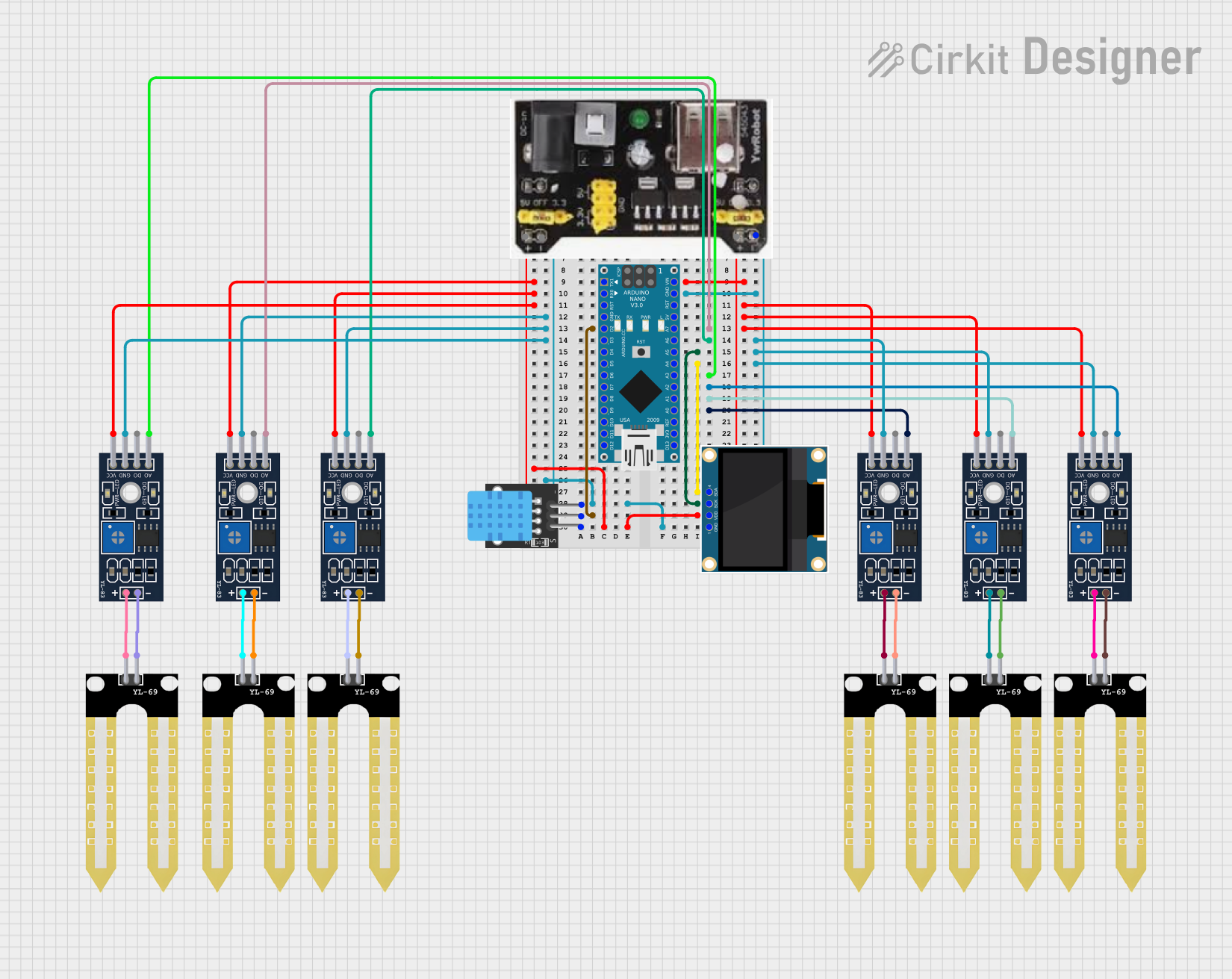
This circuit is designed to collect environmental data using multiple YL-83 modules with YL-69 sondas for soil moisture, and a KY-015 DHT11 sensor for humidity and temperature, all interfaced with an Arduino Nano. Data from the sensors is processed by the Arduino and displayed on an OLED screen, with power supplied by an MB102 Breadboard Power Supply Module.
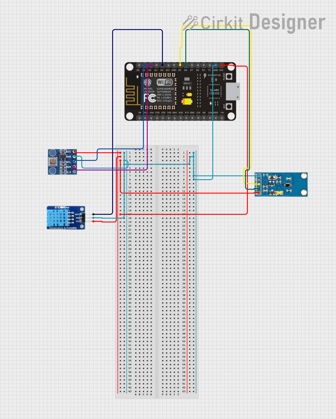
This circuit is designed to collect environmental data using an ESP-8266 microcontroller connected to a BMP180 barometric pressure sensor, a GY-30 BH1750FVI digital light intensity sensor, and a DHT11 temperature and humidity sensor. The sensors are interfaced with the ESP-8266 via I2C (SCL and SDA lines) and digital IO pins, and they share a common power supply (3.3V) and ground. The circuit is likely intended for weather monitoring or home automation applications, with capabilities to measure temperature, humidity, barometric pressure, and light intensity.
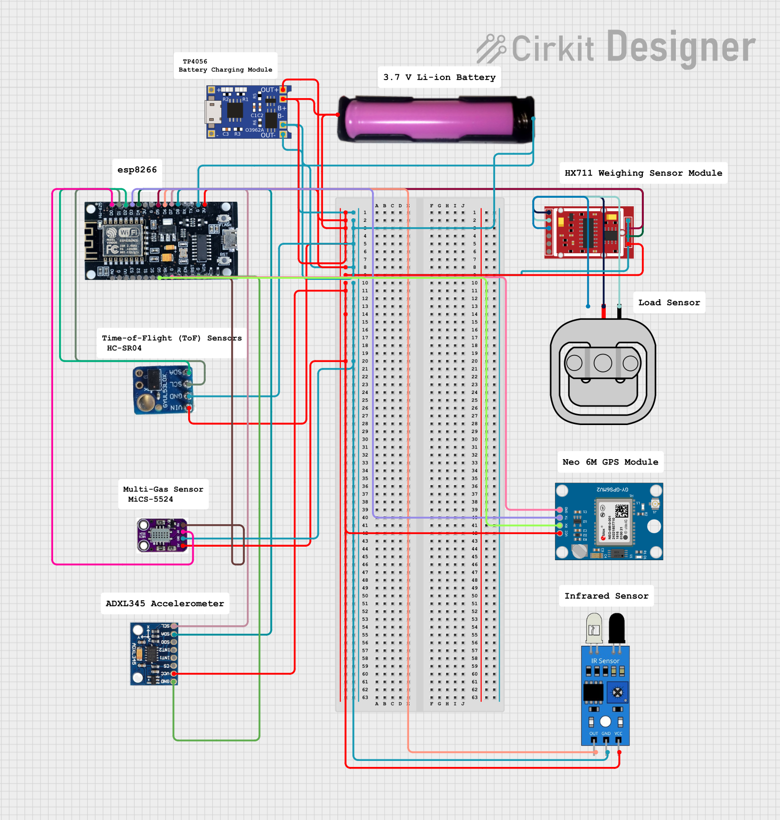
This circuit is a multi-sensor data acquisition system powered by a 18650 battery and managed by an ESP8266 microcontroller. It includes a load sensor interfaced with an HX711 module for weight measurement, an IR sensor, an ADXL345 accelerometer, a VL53L0X distance sensor, and a Neo 6M GPS module for location tracking. The system is designed for wireless data transmission and is supported by a TP4056 module for battery charging.
The GY-63 module has 6 pins, as described in the table below:
Pin Name
Description
VCC
Power supply input (3.3V to 5V)
GND
Ground connection
SCL
Serial Clock Line for I²C communication or SPI clock input (SCK)
SDA
Serial Data Line for I²C communication or SPI data input/output (MOSI/MISO)
CSB
Chip Select for SPI (active low). Tie to VCC for I²C mode (default)
PS
Protocol Select: Connect to GND for SPI, or VCC for I²C (default)
Usage Instructions
How to Use the Component in a Circuit
Power Supply: Connect the VCC pin to a 3.3V or 5V power source and the GND pin to ground.
Communication Protocol:
For I²C mode (default):
Connect the SCL pin to the I²C clock line of your microcontroller.
Connect the SDA pin to the I²C data line of your microcontroller.
Tie the CSB and PS pins to VCC.
For SPI mode:
Connect the SCL pin to the SPI clock (SCK) of your microcontroller.
Connect the SDA pin to the SPI data line (MOSI/MISO).
Connect the CSB pin to a GPIO pin on your microcontroller for chip select.
Tie the PS pin to GND.
Pull-Up Resistors: If using I²C, ensure pull-up resistors (typically 4.7kΩ) are connected to the SCL and SDA lines.
Initialization: Configure the microcontroller to communicate with the sensor using the chosen protocol. The default I²C address is 0x76 or 0x77 (depending on the module configuration).
Important Considerations and Best Practices
Voltage Compatibility: Ensure the microcontroller's logic levels are compatible with the module's operating voltage.
Noise Reduction: Use decoupling capacitors (e.g., 0.1µF) near the power pins to reduce noise.
Altitude Calculation: To calculate altitude, use the pressure readings and the barometric formula.
Temperature Compensation: The sensor provides raw pressure and temperature data. Use the manufacturer's compensation formulas for accurate results.
Example Code for Arduino UNO (I²C Mode)
#include <Wire.h>

// I2C address of the MS5611 sensor
#define MS5611_ADDRESS 0x76

void setup() {
  Wire.begin(); // Initialize I2C communication
  Serial.begin(9600); // Start serial communication for debugging

  // Reset the sensor
  Wire.beginTransmission(MS5611_ADDRESS);
  Wire.write(0x1E); // Reset command
  Wire.endTransmission();
  delay(10); // Wait for reset to complete
}

void loop() {
  // Request pressure data
  Wire.beginTransmission(MS5611_ADDRESS);
  Wire.write(0x48); // Command to start pressure conversion (OSR=4096)
  Wire.endTransmission();
  delay(10); // Wait for conversion to complete

  // Read pressure data
  Wire.beginTransmission(MS5611_ADDRESS);
  Wire.write(0x00); // Command to read ADC result
  Wire.endTransmission();
  Wire.requestFrom(MS5611_ADDRESS, 3); // Request 3 bytes of data

  if (Wire.available() == 3) {
    uint32_t pressure = 0;
    pressure = Wire.read(); // MSB
    pressure = (pressure << 8) | Wire.read(); // LSB
    pressure = (pressure << 8) | Wire.read(); // XLSB
    pressure = pressure >> 4; // 20-bit result

    Serial.print("Pressure (raw): ");
    Serial.println(pressure);
  }

  delay(1000); // Wait 1 second before the next reading
}
Troubleshooting and FAQs
Common Issues and Solutions
No Data from the Sensor:
Ensure the VCC and GND pins are properly connected.
Verify the I²C address (0x76 or 0x77) matches the module's configuration.
Check for proper pull-up resistors on the SCL and SDA lines.
Incorrect Pressure or Temperature Readings:
Ensure the sensor is not exposed to rapid temperature changes or vibrations.
Use the manufacturer's compensation formulas for accurate readings.
Communication Errors:
Verify the protocol selection (PS pin) and wiring.
Check for loose connections or damaged wires.
FAQs
Q: Can the GY-63 module operate at 5V logic levels?
A: Yes, the module includes a voltage regulator and level shifters, allowing it to work with 3.3V and 5V systems.
Q: How do I switch between I²C and SPI modes?
A: Set the PS pin to VCC for I²C mode (default) or GND for SPI mode. Ensure the CSB pin is configured accordingly.
Q: What is the maximum altitude the sensor can measure?
A: The sensor can measure up to approximately 9,000 meters above sea level, depending on atmospheric conditions.
Q: Can I use the GY-63 module outdoors?
A: Yes, but ensure the module is protected from moisture and extreme environmental conditions.


 Open Project in Cirkit Designer