How to Use SCT013 : Examples, Pinouts, and Specs
Introduction
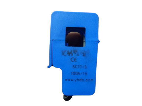
The SCT013, manufactured by YHDC, is a non-invasive AC current sensor designed for measuring alternating current (AC) in the range of 10A to 100A. This current transformer provides electrical isolation, ensuring safe and accurate current measurement without requiring direct electrical contact with the conductor. The SCT013 is widely used in energy monitoring systems, home automation, and industrial applications where real-time current measurement is essential.
Explore Projects Built with SCT013


Explore Projects Built with SCT013
Common Applications
- Energy monitoring in residential, commercial, and industrial environments
- Home automation systems for tracking power consumption
- Overcurrent protection and fault detection in electrical systems
- Load monitoring for appliances and machinery
Technical Specifications
The SCT013 is a versatile and reliable current transformer with the following key specifications:
| Parameter | Value |
|---|---|
| Manufacturer | YHDC |
| Part Number | SCT-013 |
| Current Measurement Range | 10A to 100A AC |
| Output Signal | Voltage (0-1V or 0-50mA, depending on model) |
| Core Material | Ferrite |
| Accuracy | ±1% (typical) |
| Dielectric Strength | 6000V AC |
| Operating Temperature | -25°C to +70°C |
| Cable Length | 1 meter |
| Dimensions | 13mm x 13mm (inner diameter) |
Pin Configuration and Descriptions
The SCT013 has a simple interface with two output wires. The pin configuration is as follows:
| Wire Color | Description |
|---|---|
| Blue | Signal output (AC voltage proportional to current) |
| White | Signal ground |
Note: Some models of the SCT013 include a built-in burden resistor, while others require an external burden resistor to convert the current signal to a measurable voltage.
Usage Instructions
How to Use the SCT013 in a Circuit
Connect the Sensor to the Conductor:
- Open the clamp of the SCT013 and place it around the live or neutral wire of the AC circuit you want to measure. Ensure the clamp is securely closed for accurate readings.
- Do not place the sensor around both live and neutral wires simultaneously, as this will result in a net current of zero.
Connect the Output Wires:
- If your SCT013 model has a built-in burden resistor, connect the blue wire to the analog input of your microcontroller (e.g., Arduino) and the white wire to the ground (GND).
- If your model does not have a built-in burden resistor, connect an appropriate resistor (e.g., 33Ω for a 5V system) across the output wires to convert the current signal to a voltage signal.
Calibrate the Sensor:
- Use a known current source to calibrate the sensor and ensure accurate measurements. Adjust the calibration factor in your software accordingly.
Read the Output Signal:
- The output signal is an AC voltage proportional to the current flowing through the conductor. Use an analog-to-digital converter (ADC) to read the signal and calculate the RMS current.
Important Considerations and Best Practices
- Electrical Isolation: The SCT013 provides electrical isolation, but ensure that the conductor being measured is properly insulated to avoid safety hazards.
- Burden Resistor: Verify whether your SCT013 model includes a built-in burden resistor. If not, add an external resistor as per the manufacturer's recommendations.
- Signal Filtering: Use a low-pass filter in your circuit to remove noise from the output signal for more accurate readings.
- Avoid Overloading: Do not exceed the maximum current rating of the sensor (100A) to prevent damage.
Example: Using the SCT013 with an Arduino UNO
Below is an example code snippet for using the SCT013 with an Arduino UNO to measure AC current:
// Include the EmonLib library for energy monitoring
#include "EmonLib.h"

// Create an instance of the EnergyMonitor class
EnergyMonitor emon1;

void setup() {
  Serial.begin(9600); // Initialize serial communication at 9600 baud

  // Initialize the SCT013 sensor
  // Arguments: analog pin, calibration factor
  emon1.current(A0, 111.1);
  // Calibration factor depends on the burden resistor and sensor model
}

void loop() {
  // Read the RMS current value
  double Irms = emon1.calcIrms(1480);
  // 1480 samples for a 50Hz signal (adjust for your system)

  // Print the current value to the serial monitor
  Serial.print("Current: ");
  Serial.print(Irms);
  Serial.println(" A");

  delay(1000); // Wait for 1 second before the next reading
}
Note: The calibration factor (e.g.,
111.1) must be adjusted based on your specific SCT013 model and burden resistor.
Troubleshooting and FAQs
Common Issues and Solutions
No Output Signal:
- Ensure the SCT013 is securely clamped around the conductor.
- Verify that the conductor is carrying current and is not a neutral wire with no load.
Inaccurate Readings:
- Check the calibration factor in your software and adjust it using a known current source.
- Ensure the burden resistor value matches the manufacturer's recommendations.
Noise in the Output Signal:
- Add a low-pass filter to the circuit to reduce high-frequency noise.
- Keep the sensor and its wires away from sources of electromagnetic interference (EMI).
Sensor Overheating:
- Ensure the current flowing through the conductor does not exceed the sensor's maximum rating of 100A.
FAQs
Q: Can the SCT013 measure DC current?
A: No, the SCT013 is designed for AC current measurement only. It cannot measure direct current (DC).
Q: What is the purpose of the burden resistor?
A: The burden resistor converts the current signal from the SCT013 into a measurable voltage signal. Some models include a built-in burden resistor, while others require an external resistor.
Q: Can I use the SCT013 with a Raspberry Pi?
A: Yes, but since the Raspberry Pi lacks an analog-to-digital converter (ADC), you will need an external ADC module (e.g., MCP3008) to read the sensor's output.
Q: How do I calculate power consumption using the SCT013?
A: To calculate power, you need to measure both current (using the SCT013) and voltage. Multiply the RMS current by the RMS voltage and the power factor to obtain real power (in watts).
By following this documentation, you can effectively use the SCT013 for safe and accurate AC current measurement in various applications.