
How to Use HW-685: Examples, Pinouts, and Specs
 Design with HW-685 in Cirkit Designer
Introduction
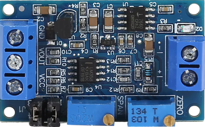
The HW-685 is a versatile electronic component often used in various circuit applications, known for its reliability and efficiency in signal processing. This module is widely utilized in projects requiring signal amplification, filtering, or conditioning. Its compact design and robust performance make it a popular choice among hobbyists and professionals alike.
Explore Projects Built with HW-685
 Open Project in Cirkit Designer
 Open Project in Cirkit Designer
 Open Project in Cirkit Designer
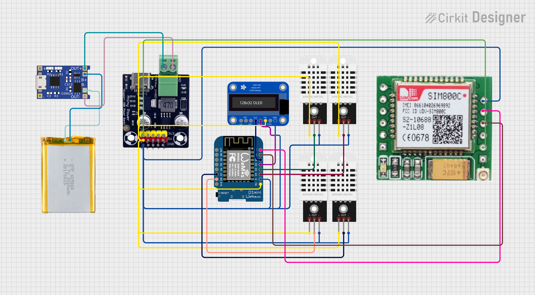 Open Project in Cirkit Designer
Explore Projects Built with HW-685
Open Project in Cirkit DesignerOpen Project in Cirkit DesignerOpen Project in Cirkit DesignerOpen Project in Cirkit DesignerCommon Applications
- Signal amplification in audio and communication systems
- Filtering and conditioning of analog signals
- Integration into microcontroller-based projects
- General-purpose signal processing in embedded systems
Technical Specifications
Below are the key technical details of the HW-685 module:
| Parameter | Value |
|---|---|
| Operating Voltage | 3.3V to 5V |
| Operating Current | 10mA (typical) |
| Signal Gain | Adjustable (via onboard potentiometer) |
| Frequency Range | 20Hz to 20kHz |
| Dimensions | 25mm x 20mm x 10mm |
| Operating Temperature | -40°C to 85°C |
Pin Configuration and Descriptions
The HW-685 module typically has a 4-pin interface. Below is the pinout description:
| Pin | Name | Description |
|---|---|---|
| 1 | VCC | Power supply input (3.3V to 5V) |
| 2 | GND | Ground connection |
| 3 | IN | Signal input |
| 4 | OUT | Signal output |
Usage Instructions
How to Use the HW-685 in a Circuit
- Power Supply: Connect the
VCCpin to a 3.3V or 5V power source and theGNDpin to the ground of your circuit. - Signal Input: Feed the analog signal to be processed into the
INpin. - Signal Output: The processed signal will be available at the
OUTpin. Connect this pin to the next stage of your circuit (e.g., an ADC or amplifier). - Adjust Gain: Use the onboard potentiometer to adjust the signal gain as needed.
Important Considerations
- Ensure the input signal does not exceed the operating voltage range to avoid damage.
- Use decoupling capacitors near the power pins to minimize noise.
- Avoid placing the module near high-frequency components to reduce interference.
- For optimal performance, keep the input and output signal traces as short as possible.
Example: Connecting HW-685 to an Arduino UNO
The HW-685 can be easily interfaced with an Arduino UNO for signal processing tasks. Below is an example code snippet to read the output signal using the Arduino's ADC:
// Define the analog pin connected to the HW-685 OUT pin
const int hw685OutputPin = A0;

void setup() {
  // Initialize serial communication for debugging
  Serial.begin(9600);
}

void loop() {
  // Read the analog value from the HW-685 output
  int signalValue = analogRead(hw685OutputPin);

  // Print the signal value to the Serial Monitor
  Serial.print("Signal Value: ");
  Serial.println(signalValue);

  // Add a small delay to stabilize readings
  delay(100);
}
Note: Ensure the IN pin of the HW-685 is connected to the signal source, and the OUT pin is connected to the Arduino's analog input pin (e.g., A0).
Troubleshooting and FAQs
Common Issues
No Output Signal:
- Verify that the
VCCandGNDpins are properly connected. - Check if the input signal is within the acceptable range.
- Ensure the onboard potentiometer is not set to zero gain.
- Verify that the
Distorted Output Signal:
- Reduce the input signal amplitude if it exceeds the module's limits.
- Adjust the potentiometer to an appropriate gain level.
- Check for noise or interference from nearby components.
Module Overheating:
- Ensure the operating voltage does not exceed 5V.
- Verify that the module is not drawing excessive current due to a short circuit.
FAQs
Q1: Can the HW-685 process digital signals?
A1: No, the HW-685 is designed for analog signal processing. Digital signals should be converted to analog before input.
Q2: What is the maximum gain of the HW-685?
A2: The maximum gain depends on the onboard potentiometer setting. Refer to the module's datasheet for precise gain values.
Q3: Can I use the HW-685 with a 12V power supply?
A3: No, the HW-685 operates within a voltage range of 3.3V to 5V. Using a higher voltage may damage the module.
Q4: How do I reduce noise in the output signal?
A4: Use decoupling capacitors near the power pins and keep signal traces short. Additionally, ensure proper grounding in your circuit.
By following this documentation, you can effectively integrate the HW-685 into your projects and troubleshoot common issues with ease.