How to Use 1528-2432-ND EVAL BOARD FOR MAX31865: Examples, Pinouts, and Specs
Introduction
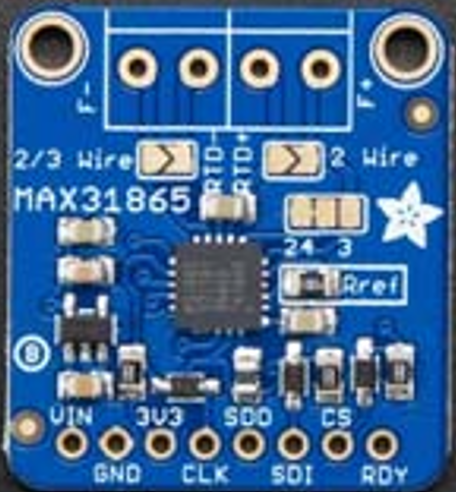
The 1528-2432-ND Evaluation Board, manufactured by Adafruit Industries LLC, is a development platform for the MAX31865, a precision RTD-to-Digital converter. This board simplifies the process of prototyping and testing temperature sensing applications using RTDs (Resistance Temperature Detectors). It is designed to work seamlessly with PT100 and PT1000 RTDs, offering high accuracy and ease of integration into various projects.
Explore Projects Built with 1528-2432-ND EVAL BOARD FOR MAX31865


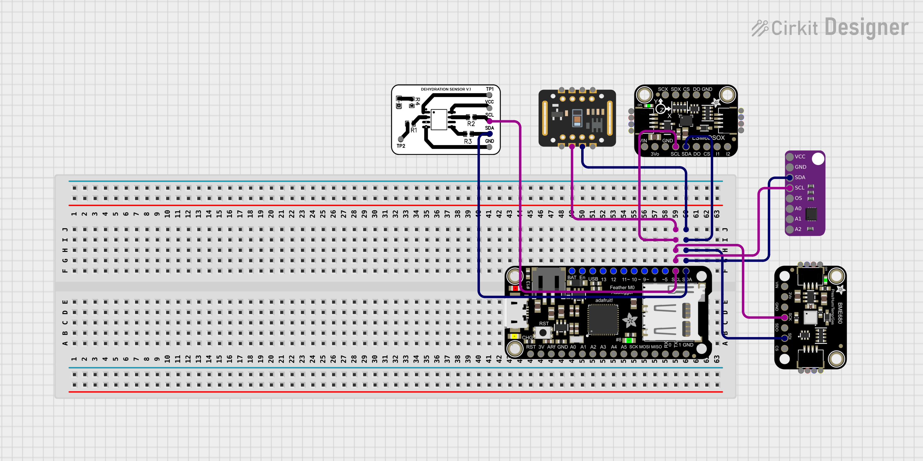
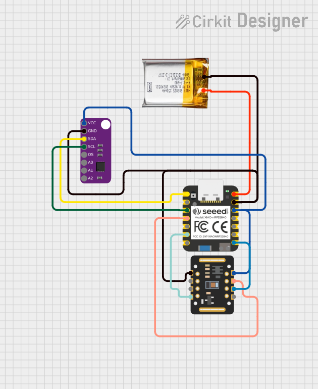
Explore Projects Built with 1528-2432-ND EVAL BOARD FOR MAX31865
Common Applications and Use Cases
- Industrial temperature monitoring and control
- HVAC systems
- Laboratory-grade temperature measurement
- IoT temperature sensing applications
- Educational and prototyping purposes
Technical Specifications
The following table outlines the key technical details of the 1528-2432-ND Evaluation Board:
| Parameter | Specification |
|---|---|
| Supported RTD Types | PT100, PT1000 |
| RTD Configuration | 2-wire, 3-wire, or 4-wire |
| Operating Voltage | 3.3V or 5V |
| Communication Interface | SPI (Serial Peripheral Interface) |
| Temperature Measurement Range | -200°C to +850°C (dependent on RTD type) |
| Accuracy | ±0.1°C (typical, depending on RTD and configuration) |
| Dimensions | 25mm x 25mm |
Pin Configuration and Descriptions
The evaluation board features the following pinout for easy integration:
| Pin | Name | Description |
|---|---|---|
| 1 | VIN | Power input (3.3V or 5V) |
| 2 | GND | Ground connection |
| 3 | SCK | SPI Clock input |
| 4 | SDI/MOSI | SPI Data input (Master Out Slave In) |
| 5 | SDO/MISO | SPI Data output (Master In Slave Out) |
| 6 | CS | Chip Select (active low) |
| 7 | RTD+ | Positive terminal for RTD connection |
| 8 | RTD- | Negative terminal for RTD connection |
| 9 | 3W/4W | Jumper for selecting 3-wire or 4-wire RTD configuration |
Usage Instructions
How to Use the Component in a Circuit
- Power the Board: Connect the VIN pin to a 3.3V or 5V power source and the GND pin to ground.
- Connect the RTD: Attach the RTD sensor to the RTD+ and RTD- terminals. For 3-wire or 4-wire RTDs, configure the jumper appropriately.
- SPI Communication: Connect the SCK, SDI/MOSI, SDO/MISO, and CS pins to the corresponding SPI pins on your microcontroller or development board.
- Load the Driver: If using an Arduino or similar platform, install the Adafruit MAX31865 library for easy integration.
- Read Temperature Data: Use the provided library functions to read and process temperature data from the RTD.
Important Considerations and Best Practices
- Ensure the RTD is properly connected and configured (2-wire, 3-wire, or 4-wire) for accurate readings.
- Use shielded cables for RTD connections in noisy environments to minimize interference.
- Avoid exceeding the operating voltage range (3.3V or 5V) to prevent damage to the board.
- Calibrate the system if high precision is required for your application.
Example Code for Arduino UNO
Below is an example of how to use the 1528-2432-ND Evaluation Board with an Arduino UNO:
#include <Adafruit_MAX31865.h>

// Define SPI pins for Arduino UNO
#define MAX31865_CS   10  // Chip Select pin
#define MAX31865_MOSI 11  // Master Out Slave In
#define MAX31865_MISO 12  // Master In Slave Out
#define MAX31865_SCK  13  // SPI Clock

// Create an instance of the MAX31865 class
Adafruit_MAX31865 max31865 = Adafruit_MAX31865(MAX31865_CS);

// Set RTD type (PT100 or PT1000)
#define RTD_TYPE PT100

void setup() {
  Serial.begin(9600);
  Serial.println("MAX31865 RTD Reader");

  // Initialize the MAX31865 board
  if (!max31865.begin(MAX31865_3WIRE)) {
    Serial.println("Failed to initialize MAX31865. Check connections.");
    while (1);
  }
}

void loop() {
  // Read temperature in Celsius
  float temperature = max31865.temperature(100.0, RTD_TYPE);

  // Print temperature to Serial Monitor
  Serial.print("Temperature: ");
  Serial.print(temperature);
  Serial.println(" °C");

  delay(1000); // Wait 1 second before next reading
}
Troubleshooting and FAQs
Common Issues Users Might Face
No Temperature Reading:
- Cause: Incorrect wiring or RTD configuration.
- Solution: Double-check all connections and ensure the RTD is properly connected.
Inaccurate Temperature Measurements:
- Cause: Incorrect RTD type or configuration.
- Solution: Verify the RTD type (PT100 or PT1000) and ensure the jumper is set correctly for 2-wire, 3-wire, or 4-wire mode.
SPI Communication Failure:
- Cause: Incorrect SPI pin connections or mismatched voltage levels.
- Solution: Ensure the SPI pins are correctly connected and the voltage levels match your microcontroller.
Board Overheating:
- Cause: Exceeding the operating voltage range.
- Solution: Use a regulated 3.3V or 5V power supply.
Solutions and Tips for Troubleshooting
- Use a multimeter to verify continuity and proper connections.
- Check the Serial Monitor for error messages or debug information.
- Update the Adafruit MAX31865 library to the latest version for compatibility and bug fixes.
- If using long cables for the RTD, consider adding a low-pass filter to reduce noise.
By following this documentation, users can effectively utilize the 1528-2432-ND Evaluation Board for MAX31865 in their temperature sensing applications.