How to Use Adafruit SHARP Memory Display 1.3 inch 96x96: Examples, Pinouts, and Specs
Introduction
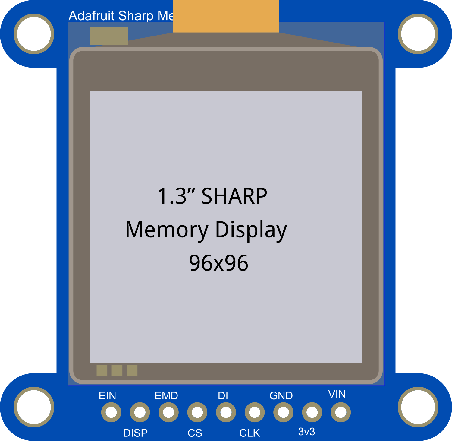
The Adafruit SHARP Memory Display is a cutting-edge display module that leverages Sharp's Memory LCD technology to deliver crisp, high-resolution visuals. With a 1.3-inch diagonal screen and a resolution of 96x96 pixels, this display is ideal for applications requiring a compact yet clear display. The built-in controller maintains pixel data in memory, enabling the display to operate on low power, making it suitable for battery-powered devices. The module's compatibility with standard SPI and I2C interfaces allows for easy integration with a variety of microcontrollers, including the popular Arduino UNO.
Explore Projects Built with Adafruit SHARP Memory Display 1.3 inch 96x96


Explore Projects Built with Adafruit SHARP Memory Display 1.3 inch 96x96
Common Applications and Use Cases
- Wearable devices
- Portable instrumentation
- Battery-powered applications
- User interfaces for small-scale projects
Technical Specifications
Key Technical Details
- Display Size: 1.3 inches diagonal
- Resolution: 96x96 pixels
- Interface: SPI/I2C
- Operating Voltage: 3.3V
- Current Consumption: 10 µA (typical when static)
- Refresh Rate: 1 Hz to 60 Hz
Pin Configuration and Descriptions
| Pin Number | Name | Description |
|---|---|---|
| 1 | GND | Ground connection |
| 2 | VIN | Power supply (3.3V) |
| 3 | 3Vo | 3.3V output from onboard regulator |
| 4 | CLK | SPI clock |
| 5 | MOSI | SPI Master Out Slave In |
| 6 | CS | SPI Chip Select |
| 7 | EXTMODE | External mode selection (Low for SPI) |
| 8 | DISP | Display on/off control |
| 9 | EXTCOMIN | External COM inversion signal |
Usage Instructions
How to Use the Component in a Circuit
Power Connections: Connect the VIN pin to a 3.3V power supply and GND to the ground. Do not exceed the recommended voltage as it may damage the display.
Data Connections: For SPI communication, connect the CLK, MOSI, and CS pins to the corresponding SPI pins on your microcontroller. For I2C, use the appropriate I2C pins (SDA and SCL), noting that additional setup may be required for I2C operation.
Control Pins: The EXTMODE pin should be connected to ground for SPI mode. The DISP pin can be connected to a digital output on your microcontroller to turn the display on or off. The EXTCOMIN pin is used for external COM inversion and may be toggled or connected to a PWM signal if required.
Important Considerations and Best Practices
- Always ensure that the power supply is stable and within the specified voltage range.
- Use a level shifter if you are interfacing with a 5V microcontroller to protect the 3.3V logic of the display.
- Keep the SPI clock speed within the display's limits to ensure proper operation.
- Avoid exposing the display to direct sunlight for extended periods to prevent damage.
Example Code for Arduino UNO
#include <Adafruit_SharpMem.h>

// SHARP Memory Display connections
#define SHARP_SCK  13  // SPI Clock
#define SHARP_MOSI 11  // SPI Data
#define SHARP_SS   10  // SPI Chip Select

// Create display object
Adafruit_SharpMem display(SHARP_SCK, SHARP_MOSI, SHARP_SS, 96, 96);

void setup() {
  display.begin();
  display.setRotation(2); // Set if needed
}

void loop() {
  display.clearDisplay(); // Clear the buffer

  // Draw a pixel in each corner
  display.drawPixel(0, 0, BLACK);
  display.drawPixel(95, 0, BLACK);
  display.drawPixel(0, 95, BLACK);
  display.drawPixel(95, 95, BLACK);

  // Write 'Hello, World!' in the center of the screen
  display.setTextSize(1);
  display.setTextColor(BLACK);
  display.setCursor(20, 45);
  display.print("Hello, World!");

  display.refresh(); // Refresh the screen to display changes
  delay(1000); // Wait for a second
}
Troubleshooting and FAQs
Common Issues
- Display Not Powering On: Check the power connections and ensure the voltage is 3.3V.
- No Image or Corrupted Image: Verify the SPI connections and ensure the correct pins are used.
- Flickering Display: Ensure that the refresh rate is set correctly and that the EXTCOMIN pin is being driven properly.
Solutions and Tips for Troubleshooting
- Double-check all connections and ensure they are secure.
- Use a multimeter to verify the voltage levels at the display pins.
- Consult the datasheet for the display to ensure correct timing and signal levels.
- If using I2C, ensure that pull-up resistors are in place and that the I2C address is correct.
FAQs
Q: Can I use this display with a 5V microcontroller? A: Yes, but you must use a level shifter to convert the 5V signals to 3.3V to avoid damaging the display.
Q: How can I save power when using this display? A: The display retains the image with very low power when not refreshing. Minimize refresh rates to save power.
Q: Is it possible to use this display in direct sunlight? A: The display is viewable in sunlight, but prolonged exposure to direct sunlight should be avoided to prevent damage.
Q: Can I use multiple displays with one microcontroller? A: Yes, you can use multiple displays by using separate chip select lines for each display and managing them in your code.