How to Use Simatic HMI: Examples, Pinouts, and Specs
Introduction
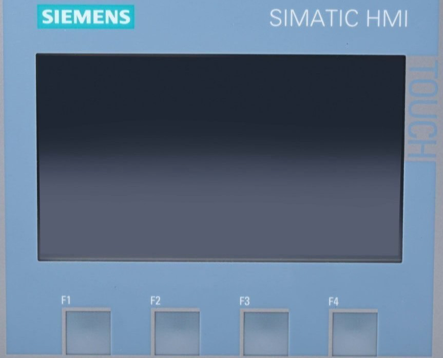
The Simatic HMI is a Human-Machine Interface (HMI) developed by Siemens, designed to facilitate the monitoring and control of industrial processes. It provides a graphical interface for operators to interact with machines, systems, and processes in real-time. The Simatic HMI is widely used in industrial automation, offering robust performance, intuitive operation, and seamless integration with Siemens PLCs and other automation systems.
Explore Projects Built with Simatic HMI


Explore Projects Built with Simatic HMI
Common Applications and Use Cases
- Industrial Automation: Monitoring and controlling production lines, machinery, and processes.
- Process Control: Supervising chemical, pharmaceutical, or food processing systems.
- Building Automation: Managing HVAC, lighting, and security systems.
- Energy Management: Monitoring power distribution and energy consumption.
- Custom Applications: Any scenario requiring user-friendly interaction with automated systems.
Technical Specifications
Key Technical Details
| Parameter | Details |
|---|---|
| Manufacturer | Siemens |
| Display Type | TFT LCD with touch functionality (varies by model) |
| Screen Sizes | 4", 7", 9", 12", 15", and larger (depending on the model) |
| Resolution | Up to Full HD (1920x1080) |
| Processor | ARM or x86-based processors (model-dependent) |
| Operating System | Windows CE, Windows Embedded, or proprietary Siemens firmware |
| Communication Protocols | PROFINET, PROFIBUS, Modbus TCP, OPC UA, Ethernet/IP, and more |
| Power Supply | 24 V DC (typical) |
| Operating Temperature | 0°C to 50°C (varies by model) |
| Ingress Protection | IP65 (front panel) |
| Certifications | CE, UL, CSA, and others (model-dependent) |
Pin Configuration and Descriptions
The Simatic HMI typically uses connectors for power, communication, and I/O. Below is a general description of the pinouts for a standard Simatic HMI model:
Power Connector
| Pin | Description |
|---|---|
| 1 | +24 V DC (Power In) |
| 2 | Ground (GND) |
Ethernet/PROFINET Connector (RJ45)
| Pin | Description |
|---|---|
| 1 | TX+ (Transmit Data +) |
| 2 | TX- (Transmit Data -) |
| 3 | RX+ (Receive Data +) |
| 6 | RX- (Receive Data -) |
Serial Communication (RS-485/RS-232, if available)
| Pin | Description |
|---|---|
| 1 | TX (Transmit Data) |
| 2 | RX (Receive Data) |
| 3 | GND (Ground) |
Note: Pin configurations may vary depending on the specific Simatic HMI model. Always refer to the official Siemens documentation for your model.
Usage Instructions
How to Use the Simatic HMI in a System
- Power Connection: Connect the HMI to a 24 V DC power supply using the designated power connector.
- Communication Setup:
- Use Ethernet/PROFINET for communication with PLCs or other devices.
- Configure the IP address and communication settings via the HMI's interface or Siemens TIA Portal software.
- Programming the HMI:
- Use Siemens TIA Portal to design and upload graphical user interfaces (GUIs) to the HMI.
- Create screens, buttons, indicators, and alarms to interact with the connected system.
- Integration with PLCs:
- Establish communication between the HMI and Siemens PLCs (e.g., S7-1200, S7-1500) using PROFINET or PROFIBUS.
- Map PLC variables to HMI elements for real-time monitoring and control.
- Testing and Deployment:
- Test the HMI functionality in a controlled environment.
- Deploy the HMI in the field and ensure proper operation.
Important Considerations and Best Practices
- Power Supply: Ensure a stable 24 V DC power source to avoid unexpected shutdowns.
- Environmental Conditions: Install the HMI in an environment within its specified operating temperature and humidity range.
- Firmware Updates: Regularly update the HMI firmware to ensure compatibility and security.
- Backup Configurations: Always back up HMI projects and configurations to avoid data loss.
- EMI Protection: Use shielded cables and proper grounding to minimize electromagnetic interference.
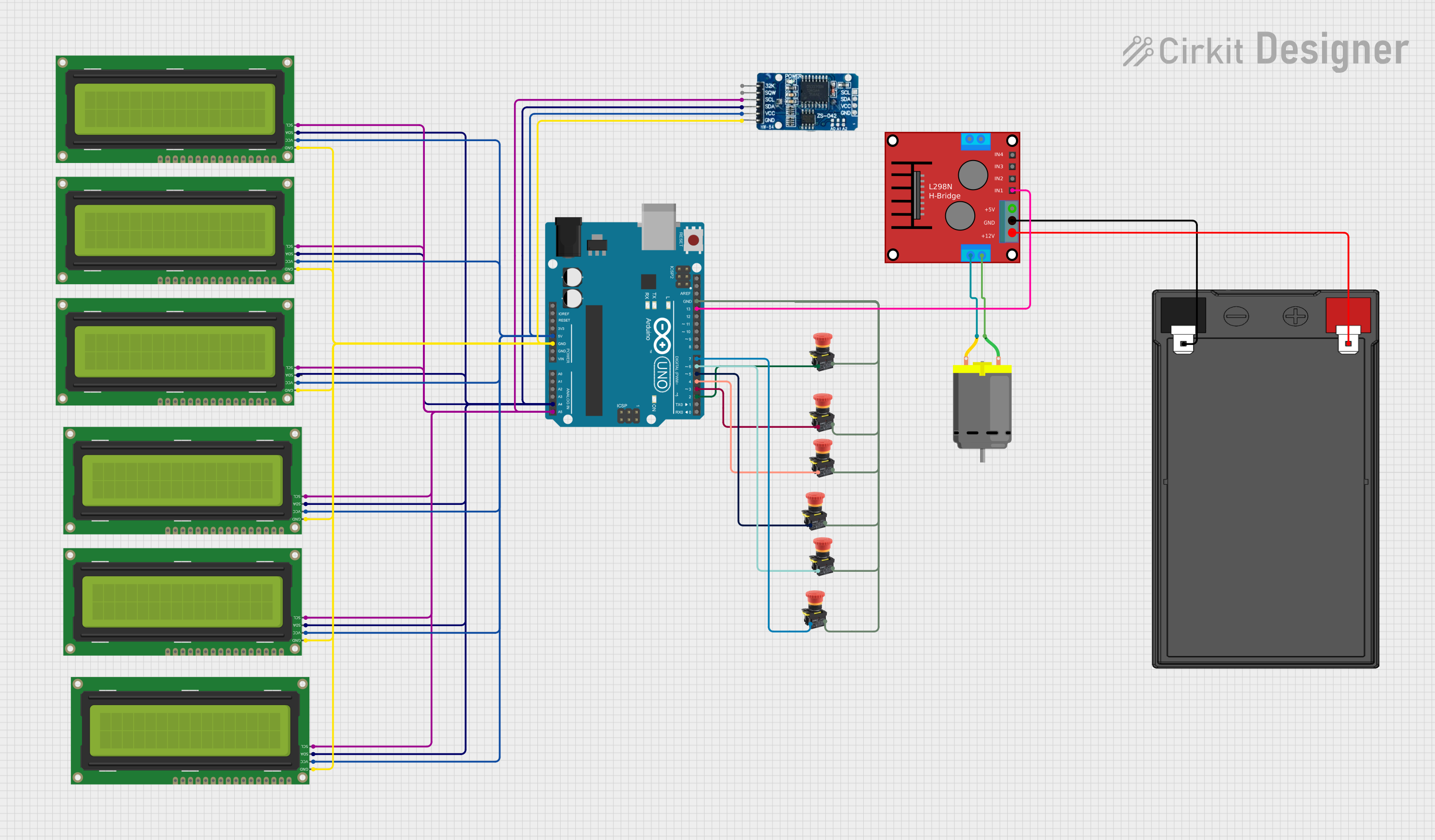
Example: Connecting Simatic HMI to an Arduino UNO
While Simatic HMIs are primarily designed for industrial PLCs, they can also communicate with microcontrollers like Arduino using Modbus or serial communication. Below is an example of using Modbus RTU with an Arduino UNO:
Arduino Code Example
#include <ModbusRtu.h>

// Define Modbus object
Modbus slave(1, Serial, 0); // Slave ID = 1, using Serial port

// Define Modbus registers
uint16_t modbusRegs[10]; // Array to hold Modbus registers

void setup() {
  Serial.begin(9600); // Initialize serial communication at 9600 baud
  slave.begin(9600);  // Initialize Modbus communication
}

void loop() {
  // Update Modbus communication
  slave.poll(modbusRegs, 10);

  // Example: Update register 0 with a value
  modbusRegs[0] = analogRead(A0); // Read analog input and store in register 0
}
Note: Configure the Simatic HMI to communicate with the Arduino using Modbus RTU. Set the HMI as the Modbus master and map the registers accordingly.
Troubleshooting and FAQs
Common Issues and Solutions
HMI Not Powering On:
- Cause: Insufficient or unstable power supply.
- Solution: Verify the power source provides 24 V DC and check the wiring.
Communication Failure with PLC:
- Cause: Incorrect IP address or communication settings.
- Solution: Double-check the IP address, subnet mask, and protocol settings in both the HMI and PLC.
Touchscreen Not Responding:
- Cause: Calibration issue or hardware fault.
- Solution: Recalibrate the touchscreen via the HMI settings or contact Siemens support.
HMI Freezes or Crashes:
- Cause: Overloaded CPU or outdated firmware.
- Solution: Reduce the number of active screens or update the firmware.
Display Issues (e.g., Flickering):
- Cause: EMI or loose connections.
- Solution: Use shielded cables and ensure all connections are secure.
FAQs
Q: Can the Simatic HMI be used with non-Siemens PLCs?
- A: Yes, the HMI supports standard protocols like Modbus and OPC UA, allowing integration with non-Siemens devices.
Q: How do I update the firmware on my Simatic HMI?
- A: Use Siemens TIA Portal or the HMI's built-in update feature. Refer to the official Siemens documentation for detailed steps.
Q: Can I use the Simatic HMI in outdoor environments?
- A: Only if the HMI model is rated for outdoor use. Check the IP rating and environmental specifications.
Q: What software is required to program the Simatic HMI?
- A: Siemens TIA Portal is the recommended software for programming and configuring Simatic HMIs.
Q: How do I back up my HMI project?
- A: Use TIA Portal to export the project file or create a backup directly on the HMI using a USB drive or SD card.