How to Use Photosensitive Sensor Module Digital Light Intensity Detection: Examples, Pinouts, and Specs
Introduction
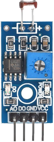
The Photosensitive Sensor Module by uxcell is an electronic component designed to measure the intensity of light in an environment and convert it into a corresponding electrical signal. This module is commonly used in applications such as automatic lighting control, daylight harvesting systems, and in devices that adjust their operation based on ambient light conditions.
Explore Projects Built with Photosensitive Sensor Module Digital Light Intensity Detection
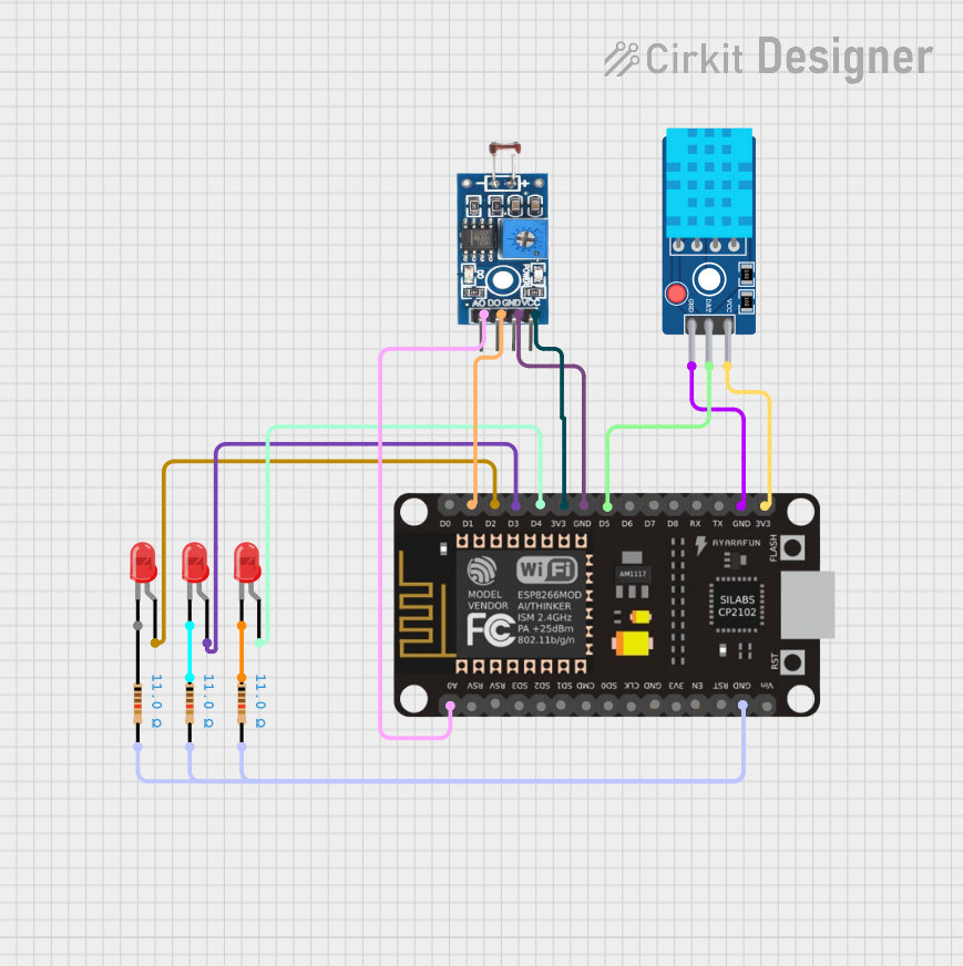
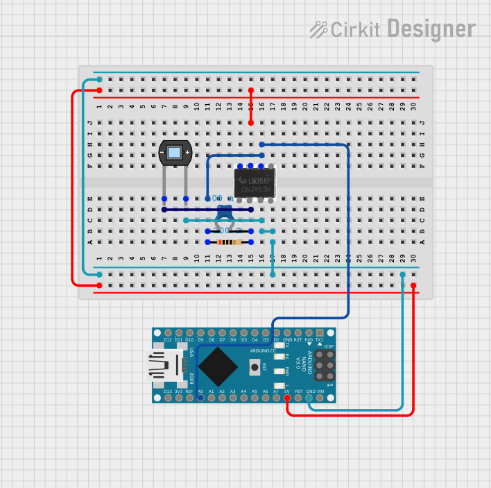
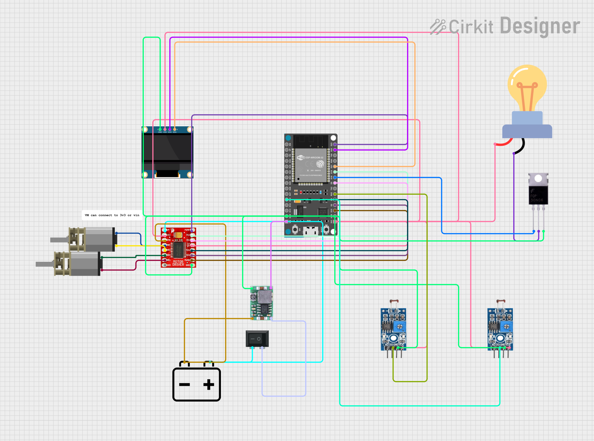
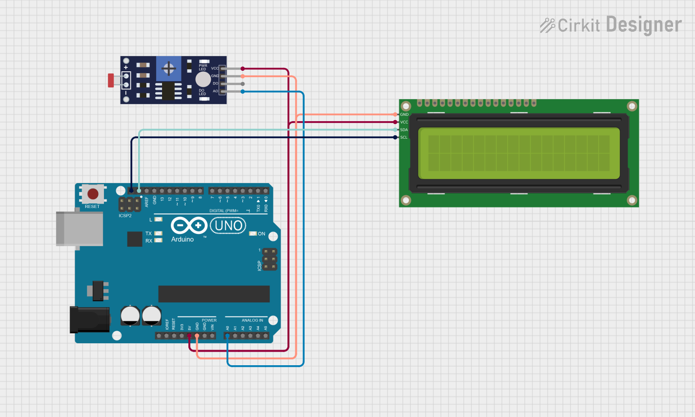
Explore Projects Built with Photosensitive Sensor Module Digital Light Intensity Detection
Common Applications and Use Cases
- Automatic brightness control in consumer electronics (e.g., smartphones, displays)
- Daylight sensing for smart lighting systems
- Environmental monitoring for greenhouses
- Security systems with light-based triggers
Technical Specifications
Key Technical Details
- Operating Voltage: 3.3V to 5V DC
- Output Voltage: 0V to 5V (relative to light intensity)
- Response Spectrum: 540nm (peak sensitivity wavelength)
- Operating Current: 15mA (typical)
- Ambient Light Detection Range: 1 lux to 6000 lux
Pin Configuration and Descriptions
| Pin Number | Pin Name | Description |
|---|---|---|
| 1 | VCC | Power supply (3.3V to 5V DC) |
| 2 | GND | Ground |
| 3 | DO | Digital output (high/low based on threshold) |
| 4 | AO | Analog output (voltage proportional to light intensity) |
Usage Instructions
How to Use the Component in a Circuit
- Connect the VCC pin to a 3.3V or 5V power supply.
- Connect the GND pin to the ground of the power supply.
- The AO pin outputs an analog voltage that varies with light intensity. Connect this to an analog input on your microcontroller to read the light levels.
- The DO pin outputs a digital signal. Connect this to a digital input on your microcontroller. You can set a threshold light level at which the digital output switches from LOW to HIGH.
Important Considerations and Best Practices
- Avoid exposing the sensor to direct sunlight or strong artificial light sources that could damage the sensor.
- Ensure that the power supply is stable and within the specified voltage range to prevent damage to the module.
- When using the digital output, calibrate the threshold sensitivity using the onboard potentiometer.
Example Code for Arduino UNO
// Define the pin connected to the analog output of the sensor
const int lightSensorPin = A0;

void setup() {
  // Begin serial communication at a baud rate of 9600
  Serial.begin(9600);
}

void loop() {
  // Read the value from the light sensor
  int sensorValue = analogRead(lightSensorPin);
  // Convert the reading to voltage
  float voltage = sensorValue * (5.0 / 1023.0);
  // Print out the value in volts
  Serial.print("Voltage: ");
  Serial.println(voltage);
  // Wait for 100 milliseconds before reading again
  delay(100);
}
Troubleshooting and FAQs
Common Issues Users Might Face
- Inconsistent Readings: Ensure that the sensor is not exposed to fluctuating light sources and that connections are secure.
- No Output: Verify that the power supply is within the specified range and that the pins are correctly connected.
Solutions and Tips for Troubleshooting
- If the digital output does not seem to respond correctly, adjust the onboard potentiometer to calibrate the threshold.
- Use a multimeter to check the voltage at the VCC and GND pins to ensure proper power supply.
- Shield the sensor from direct light with a diffuser for more stable readings.
FAQs
Q: Can the sensor be used outdoors? A: Yes, but it should not be exposed to direct sunlight or harsh weather conditions without proper casing.
Q: What is the purpose of the onboard potentiometer? A: It is used to set the threshold for the digital output. When the light level exceeds this threshold, the DO pin will switch from LOW to HIGH.
Q: How do I convert the analog reading to a light intensity value? A: The analog reading is proportional to the light intensity. You can calibrate the sensor with known light levels to create a conversion factor.
Q: Is the sensor sensitive to all types of light? A: The sensor has peak sensitivity at 540nm, which is in the visible spectrum, but it can detect a range of light wavelengths.
Remember, this documentation is a starting point for working with the Photosensitive Sensor Module. Always consult the manufacturer's datasheet for the most detailed and specific information regarding the component.