How to Use Photocell Light Switch Controller AC220V10A Photo Control Sensor: Examples, Pinouts, and Specs
Introduction
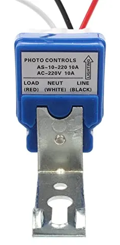
The Photocell Light Switch Controller AC220V10A Photo Control Sensor is a device designed to automatically control lighting systems based on ambient light levels. It is commonly used in outdoor lighting applications such as streetlights, garden lights, and security lighting. The sensor detects the surrounding light intensity and switches the connected lighting system on or off accordingly, ensuring energy efficiency and convenience.
This component operates at an input voltage of AC220V and supports a maximum current of 10A, making it suitable for a wide range of lighting systems. Its robust design ensures reliable operation in various environmental conditions.
Explore Projects Built with Photocell Light Switch Controller AC220V10A Photo Control Sensor

Explore Projects Built with Photocell Light Switch Controller AC220V10A Photo Control Sensor
Common Applications
- Streetlights and roadway lighting
- Garden and landscape lighting
- Security lighting for homes and businesses
- Parking lot lighting
- Signage and billboard illumination
Technical Specifications
Below are the key technical details of the Photocell Light Switch Controller:
| Parameter | Specification |
|---|---|
| Operating Voltage | AC 220V |
| Maximum Load Current | 10A |
| Power Frequency | 50/60 Hz |
| Light Sensitivity | Adjustable (factory preset) |
| Operating Temperature | -40°C to +70°C |
| Housing Material | Weatherproof plastic |
| Dimensions | Varies by model |
| Mounting Type | Screw or bracket mount |
Pin Configuration and Descriptions
The Photocell Light Switch Controller typically has three wires for connection:
| Wire Color | Function | Description |
|---|---|---|
| Red | Load (Output) | Connects to the live wire of the lighting system. |
| Black | Line (Input) | Connects to the live wire of the AC power source. |
| White | Neutral | Connects to the neutral wire of the AC power source. |
Usage Instructions
How to Use the Component in a Circuit
- Safety First: Ensure the power supply is turned off before making any connections.
- Wiring:
- Connect the black wire to the live wire of the AC power source.
- Connect the white wire to the neutral wire of the AC power source.
- Connect the red wire to the live wire of the lighting system.
- Mounting:
- Install the sensor in a location where it can accurately detect ambient light levels.
- Avoid placing the sensor in areas with direct artificial light, as this may cause incorrect operation.
- Testing:
- Turn on the power supply and observe the operation of the connected lighting system.
- The lights should turn on when the ambient light level drops below the preset threshold and turn off when the light level increases.
Important Considerations and Best Practices
- Ensure the total load current does not exceed the maximum rating of 10A.
- Install the sensor in a weather-protected area to prevent water ingress, even though the housing is weatherproof.
- Avoid placing the sensor near reflective surfaces or heat sources, as these may interfere with its operation.
- If the light sensitivity needs adjustment, refer to the manufacturer's instructions for modifying the preset threshold.
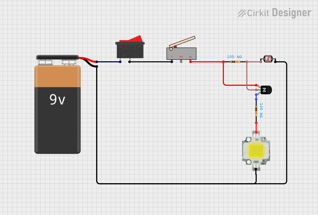
Example Arduino Integration
While this component is not directly compatible with low-voltage microcontrollers like the Arduino UNO, you can use a relay module to interface the photocell sensor with an Arduino for advanced control. Below is an example code snippet for monitoring the sensor's output using a relay:
// Example Arduino code for monitoring a photocell light switch via a relay

const int relayPin = 2; // Pin connected to the relay module
const int ledPin = 13;  // Built-in LED for status indication

void setup() {
  pinMode(relayPin, INPUT); // Set relay pin as input
  pinMode(ledPin, OUTPUT); // Set LED pin as output
  Serial.begin(9600);      // Initialize serial communication
}

void loop() {
  int sensorState = digitalRead(relayPin); // Read the relay state

  if (sensorState == HIGH) {
    digitalWrite(ledPin, HIGH); // Turn on LED if light is detected
    Serial.println("Light detected: Lights OFF");
  } else {
    digitalWrite(ledPin, LOW);  // Turn off LED if no light is detected
    Serial.println("No light detected: Lights ON");
  }

  delay(1000); // Wait for 1 second before the next reading
}
Note: Ensure proper isolation between the high-voltage AC circuit and the low-voltage Arduino circuit using a relay module.
Troubleshooting and FAQs
Common Issues and Solutions
| Issue | Possible Cause | Solution |
|---|---|---|
| Lights remain ON during the day | Sensor is not detecting ambient light properly | Ensure the sensor is not obstructed or shaded. |
| Lights flicker or turn ON/OFF intermittently | Electrical noise or unstable power supply | Use a surge protector or stabilize the power. |
| Sensor does not turn ON the lights at night | Incorrect wiring or faulty sensor | Verify wiring connections and replace the sensor if needed. |
| Sensor turns OFF lights too early | Light sensitivity is set too high | Adjust the sensitivity setting (if adjustable). |
FAQs
Can this sensor handle LED lights?
- Yes, as long as the total current does not exceed 10A.
Can I use this sensor with a DC power supply?
- No, this sensor is designed for AC220V operation only.
How do I adjust the light sensitivity?
- Some models have an adjustable screw or knob for sensitivity. Refer to the manufacturer's manual for details.
Is the sensor waterproof?
- The housing is weatherproof, but it is recommended to install the sensor in a sheltered location for extended durability.
By following this documentation, you can effectively integrate and troubleshoot the Photocell Light Switch Controller AC220V10A Photo Control Sensor in your lighting projects.