How to Use RS485 Waterproof Ambient Light Sensor: Examples, Pinouts, and Specs
Introduction
The RS485 Waterproof Ambient Light Sensor by DFRobot is a robust and reliable sensor designed to measure ambient light levels in outdoor environments. Its waterproof design ensures durability in harsh weather conditions, making it ideal for applications such as smart street lighting, outdoor environmental monitoring, and agricultural automation. The sensor communicates using the RS485 interface, which allows for long-distance, noise-resistant data transmission.
This sensor is particularly suited for scenarios where accurate light level detection is required, even in challenging environments. Its compatibility with the RS485 protocol makes it easy to integrate into industrial and IoT systems.
Explore Projects Built with RS485 Waterproof Ambient Light Sensor


Explore Projects Built with RS485 Waterproof Ambient Light Sensor
Technical Specifications
Below are the key technical details of the RS485 Waterproof Ambient Light Sensor:
| Parameter | Specification |
|---|---|
| Operating Voltage | 5V DC |
| Operating Current | ≤ 20mA |
| Communication Protocol | RS485 (Modbus RTU) |
| Light Intensity Range | 0 to 100,000 lux |
| Accuracy | ±5% |
| Waterproof Rating | IP65 |
| Operating Temperature | -40°C to 85°C |
| Cable Length | 1.5 meters |
Pin Configuration and Descriptions
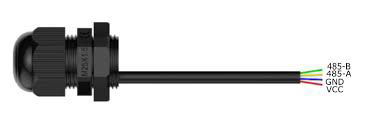
The sensor has a 4-wire cable for power and communication. The pinout is as follows:
| Wire Color | Function | Description |
|---|---|---|
| Red | VCC | Power supply (5V DC) |
| Black | GND | Ground |
| Yellow | A (RS485+) | RS485 positive data line |
| Green | B (RS485-) | RS485 negative data line |
Usage Instructions
How to Use the Component in a Circuit
- Power the Sensor: Connect the red wire to a 5V DC power source and the black wire to ground.
- RS485 Communication: Connect the yellow (A) and green (B) wires to the RS485 interface of your microcontroller or RS485-to-USB converter.
- Termination Resistor: If the sensor is at the end of the RS485 bus, connect a 120-ohm termination resistor between the A and B lines to prevent signal reflections.
- Modbus RTU Configuration: The sensor communicates using the Modbus RTU protocol. Configure your master device to query the sensor for light intensity data.
Important Considerations and Best Practices
- Waterproofing: Ensure the sensor's cable entry point is properly sealed to maintain its IP65 rating.
- Cable Length: The RS485 protocol supports long cable runs, but ensure the total length does not exceed 1,200 meters for reliable communication.
- Power Supply: Use a stable 5V DC power source to avoid fluctuations that could affect sensor performance.
- Address Configuration: If using multiple sensors on the same RS485 bus, ensure each sensor has a unique Modbus address. Refer to the manufacturer's documentation for address configuration instructions.
Example Code for Arduino UNO
Below is an example of how to interface the RS485 Waterproof Ambient Light Sensor with an Arduino UNO using an RS485-to-TTL module:
#include <ModbusMaster.h>

// Create an instance of the ModbusMaster library
ModbusMaster node;

// Define the RS485 enable pin
#define RS485_ENABLE_PIN 2

void preTransmission() {
  digitalWrite(RS485_ENABLE_PIN, HIGH); // Enable RS485 transmission
}

void postTransmission() {
  digitalWrite(RS485_ENABLE_PIN, LOW);  // Disable RS485 transmission
}

void setup() {
  Serial.begin(9600);                  // Initialize serial communication
  pinMode(RS485_ENABLE_PIN, OUTPUT);   // Set RS485 enable pin as output
  digitalWrite(RS485_ENABLE_PIN, LOW); // Set RS485 to receive mode

  node.begin(1, Serial);               // Set Modbus slave ID to 1
  node.preTransmission(preTransmission);
  node.postTransmission(postTransmission);
}

void loop() {
  uint8_t result;
  uint16_t lux;

  // Read light intensity (register 0x0000)
  result = node.readInputRegisters(0x0000, 1);

  if (result == node.ku8MBSuccess) {
    lux = node.getResponseBuffer(0);   // Get the light intensity value
    Serial.print("Ambient Light Intensity: ");
    Serial.print(lux);
    Serial.println(" lux");
  } else {
    Serial.println("Failed to read from sensor");
  }

  delay(1000); // Wait 1 second before the next reading
}
Notes on the Code
- The
ModbusMasterlibrary is used to communicate with the sensor. Install it via the Arduino Library Manager. - Adjust the Modbus slave ID (
node.begin(1, Serial)) if your sensor uses a different address. - Ensure the RS485-to-TTL module is correctly connected to the Arduino's TX, RX, and enable pins.
Troubleshooting and FAQs
Common Issues and Solutions
No Data Received from the Sensor
- Verify the RS485 connections (A and B lines) and ensure they are not swapped.
- Check the Modbus slave ID and ensure it matches the sensor's configuration.
- Ensure the termination resistor is installed if the sensor is at the end of the RS485 bus.
Incorrect Light Intensity Readings
- Ensure the sensor is not obstructed or exposed to reflective surfaces that could distort readings.
- Verify the power supply voltage is stable at 5V DC.
Communication Errors
- Check the baud rate and Modbus settings (e.g., parity, stop bits) on both the sensor and the master device.
- Ensure the total RS485 cable length does not exceed the protocol's limits.
FAQs
Q: Can this sensor be used indoors?
A: Yes, the sensor can be used indoors, but its waterproof design is optimized for outdoor applications.
Q: How do I change the Modbus address of the sensor?
A: Refer to the DFRobot user manual for instructions on configuring the Modbus address using specific Modbus commands.
Q: What is the maximum number of sensors I can connect to an RS485 bus?
A: The RS485 standard supports up to 32 devices on a single bus, but this may vary depending on the master device and cable length.
Q: Can I use a 3.3V power supply instead of 5V?
A: No, the sensor requires a 5V DC power supply for proper operation.