How to Use Rotary wafer switch 12 pin: Examples, Pinouts, and Specs
Introduction
The rotary wafer switch is a versatile electromechanical component designed to enable the selection of multiple circuit paths through a rotating mechanism. This 12-pin rotary wafer switch is commonly used in applications requiring the selection of different signal paths, such as audio equipment, test instruments, and multi-channel systems. Its compact design and reliable switching mechanism make it ideal for use in both analog and digital circuits.
Explore Projects Built with Rotary wafer switch 12 pin


Explore Projects Built with Rotary wafer switch 12 pin
Common Applications and Use Cases
- Audio equipment for selecting input/output channels
- Test and measurement devices for switching between different test points
- Multi-channel communication systems
- Mode selection in control panels
- Signal routing in electronic circuits
Technical Specifications
The following table outlines the key technical details of the rotary wafer switch:
| Parameter | Specification |
|---|---|
| Number of Pins | 12 |
| Number of Positions | Typically 1 to 12 (configurable) |
| Switching Mechanism | Rotary (manual) |
| Contact Rating | 0.3A at 125V AC / 0.5A at 30V DC |
| Insulation Resistance | ≥ 100 MΩ at 500V DC |
| Contact Resistance | ≤ 50 mΩ |
| Operating Temperature | -25°C to +85°C |
| Mounting Style | Panel mount or PCB mount |
Pin Configuration and Descriptions
The rotary wafer switch has 12 pins arranged in a circular pattern. The pin configuration is as follows:
| Pin Number | Description |
|---|---|
| 1-12 | Circuit connection points for each position |
| Common (C) | Central pin connected to the rotating contact |
- Pins 1-12: These pins correspond to the selectable positions of the switch. When the switch is rotated, the common pin (C) connects to one of these pins.
- Common (C): This is the central pin that serves as the input or output, depending on the circuit design.
Usage Instructions
How to Use the Component in a Circuit
- Determine the Required Positions: Decide how many positions (1 to 12) are needed for your application. If fewer positions are required, mechanical stops on the switch can often be adjusted to limit rotation.
- Connect the Common Pin: Connect the central pin (C) to the input or output of your circuit.
- Connect the Position Pins: Connect the desired pins (1-12) to the corresponding circuit paths.
- Mount the Switch: Secure the switch to a panel or PCB using the mounting hardware provided.
- Test the Circuit: Rotate the switch to ensure proper connection between the common pin and the selected position pin.
Important Considerations and Best Practices
- Voltage and Current Ratings: Ensure the switch is used within its rated voltage and current limits to avoid damage.
- Debouncing: In digital circuits, consider adding a debouncing circuit or software logic to handle transient signals during switching.
- Mechanical Stops: If fewer than 12 positions are needed, adjust the mechanical stops (if available) to limit the rotation range.
- Contact Cleaning: Periodically clean the contacts to maintain reliable operation, especially in environments prone to dust or corrosion.
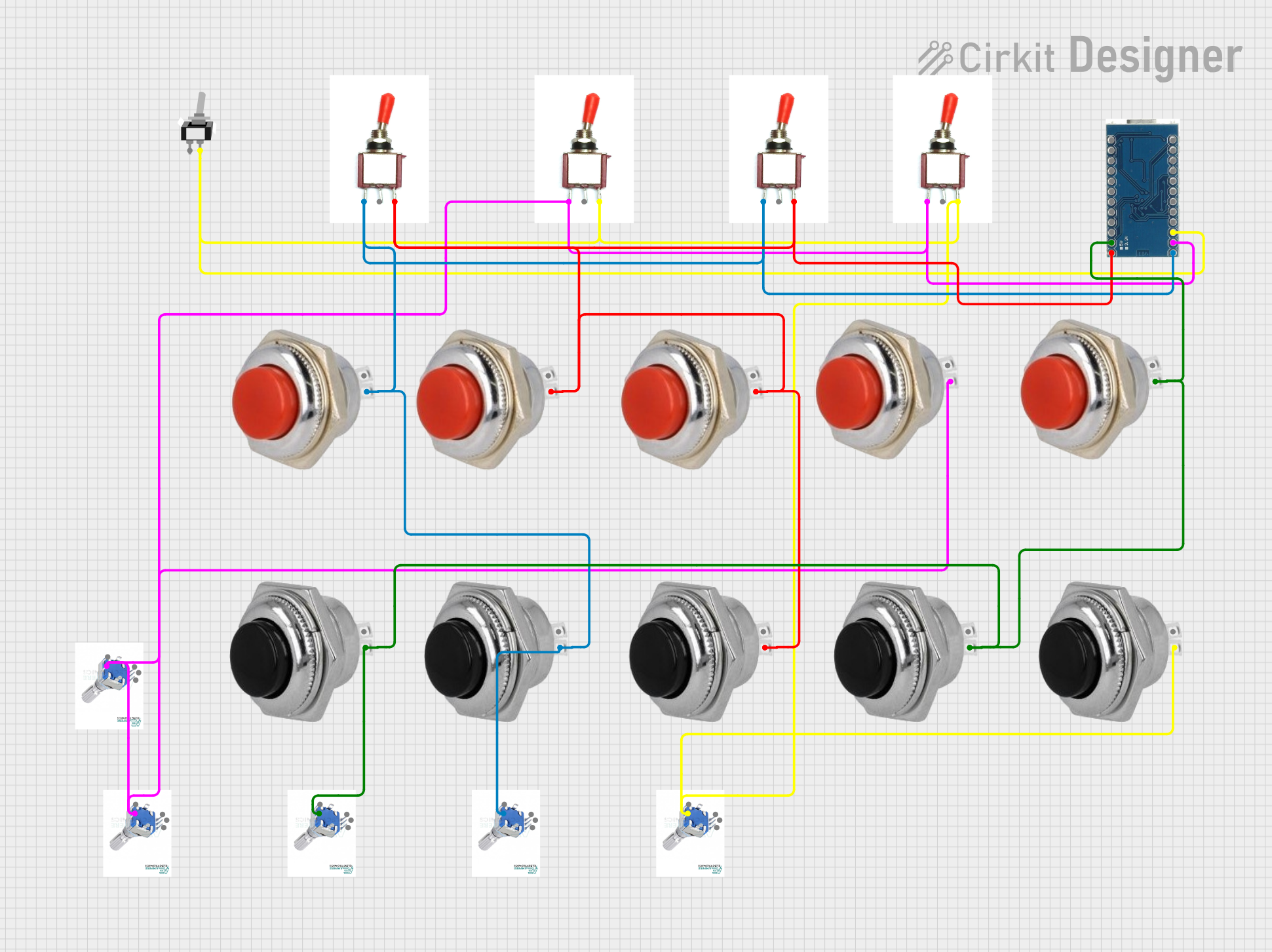
Example: Connecting to an Arduino UNO
The rotary wafer switch can be used with an Arduino UNO to read the selected position. Below is an example code snippet:
// Rotary Wafer Switch Example with Arduino UNO
// Reads the position of a 12-pin rotary wafer switch and prints it to the Serial Monitor

const int commonPin = A0; // Common pin connected to analog pin A0
const int numPositions = 12; // Total number of positions on the switch

void setup() {
  Serial.begin(9600); // Initialize serial communication
  pinMode(commonPin, INPUT); // Set the common pin as input
}

void loop() {
  int position = analogRead(commonPin); // Read the analog value from the switch
  int selectedPosition = map(position, 0, 1023, 1, numPositions);
  // Map the analog value to the switch position (1-12)

  Serial.print("Selected Position: ");
  Serial.println(selectedPosition); // Print the selected position to the Serial Monitor

  delay(500); // Delay for stability
}
Note: Use pull-down resistors on the position pins to ensure stable readings.
Troubleshooting and FAQs
Common Issues and Solutions
Switch Does Not Rotate Smoothly
- Cause: Dust or debris in the mechanism.
- Solution: Clean the switch with compressed air or contact cleaner.
Incorrect Position Detection
- Cause: Poor contact or loose connections.
- Solution: Check and secure all connections. Clean the contacts if necessary.
Signal Interference or Noise
- Cause: Lack of debouncing in digital circuits.
- Solution: Add a debouncing circuit or implement software debouncing.
Switch Fails to Operate
- Cause: Exceeding voltage/current ratings.
- Solution: Verify that the switch is used within its specified ratings.
FAQs
Q: Can I use this switch for high-power applications?
A: No, this switch is designed for low-power applications. Exceeding the rated current or voltage may damage the switch.
Q: How do I limit the number of selectable positions?
A: Many rotary wafer switches have adjustable mechanical stops. Refer to the manufacturer's instructions to configure the stops.
Q: Can this switch be used in an outdoor environment?
A: The switch is not weatherproof. For outdoor use, ensure it is enclosed in a protective housing.
Q: Is the switch suitable for high-frequency signals?
A: The switch may introduce some signal loss or noise at high frequencies. Test it in your specific application to ensure performance meets your requirements.