Cirkit Designer
Your all-in-one circuit design IDE
Home /
Component Documentation
How to Use General Corp: Examples, Pinouts, and Specs
Introduction
- General Corp is a fictional or placeholder name often used in examples or discussions related to corporate entities, business structures, or case studies in various fields such as finance, law, or business management. While not an actual electronic component, this documentation will treat it as a hypothetical electronic device for illustrative purposes.
- Common applications and use cases for this fictional component could include educational demonstrations, prototyping, or as a placeholder in circuit design examples.
Explore Projects Built with General Corp
Battery-Powered Sumo Robot with IR Sensors and DC Motors

This circuit is designed for a robotic system, featuring a Massive Sumo Board as the central controller. It integrates multiple FS-80NK diffuse IR sensors and IR line sensors for obstacle detection and line following, respectively, and controls two GM25 DC motors via MD13s motor drivers for movement. Power is supplied by an 11.1V LiPo battery.
USB-Powered DC Gear Motor with LED Indicator

This circuit appears to be a power supply unit with a bridge rectifier connected to a DC gear motor, indicating it is designed to convert AC to DC power for the motor. An electrolytic capacitor is used for smoothing the DC output, and a 7805 voltage regulator is included to provide a stable 5V output. Additionally, there is an LED with a series resistor, likely serving as a power indicator light.
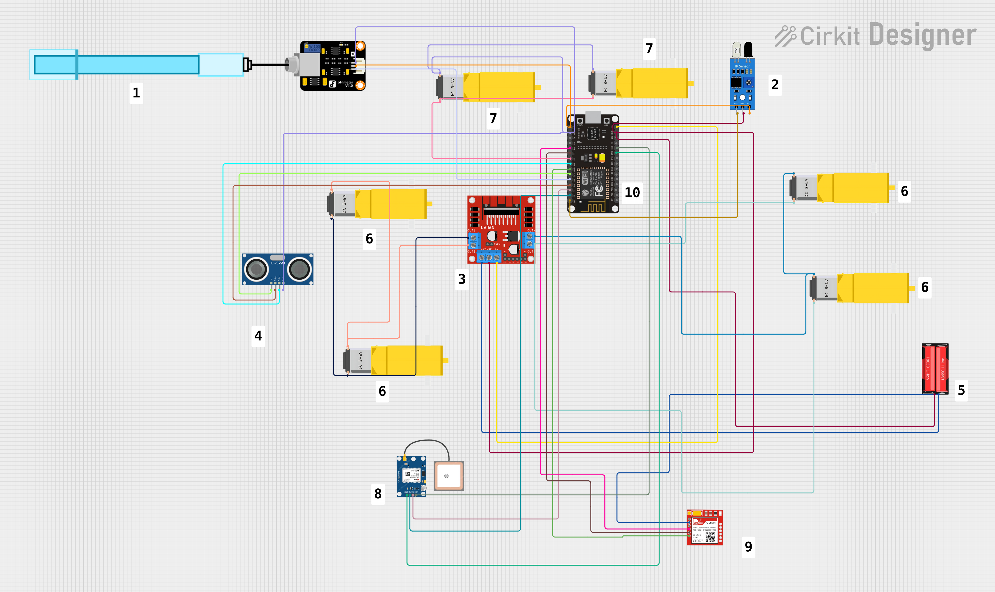
ESP8266 Controlled Robotics Platform with GPS, IR, and GSM Features
This is a microcontroller-based control system designed for a mobile robotic platform with environmental sensing, location tracking, and GSM communication capabilities. It includes motor control for actuation, various sensors for data acquisition, and a battery for power supply.
ESP32-Controlled Multi-Display Interactive System with Pushbutton Inputs

This circuit consists of multiple GC9A01 display modules interfaced with an ESP32 microcontroller. The ESP32 controls the reset (RST), chip select (CS), data/command (DC), serial data (SDA), and serial clock (SCL) lines of each display, allowing for individual communication with each screen. Additionally, there are pushbuttons connected to the ESP32, which could be used for user input to control the displays or other functions within the circuit.
Explore Projects Built with General Corp
Battery-Powered Sumo Robot with IR Sensors and DC Motors
This circuit is designed for a robotic system, featuring a Massive Sumo Board as the central controller. It integrates multiple FS-80NK diffuse IR sensors and IR line sensors for obstacle detection and line following, respectively, and controls two GM25 DC motors via MD13s motor drivers for movement. Power is supplied by an 11.1V LiPo battery.
USB-Powered DC Gear Motor with LED Indicator
This circuit appears to be a power supply unit with a bridge rectifier connected to a DC gear motor, indicating it is designed to convert AC to DC power for the motor. An electrolytic capacitor is used for smoothing the DC output, and a 7805 voltage regulator is included to provide a stable 5V output. Additionally, there is an LED with a series resistor, likely serving as a power indicator light.
ESP8266 Controlled Robotics Platform with GPS, IR, and GSM Features
This is a microcontroller-based control system designed for a mobile robotic platform with environmental sensing, location tracking, and GSM communication capabilities. It includes motor control for actuation, various sensors for data acquisition, and a battery for power supply.
ESP32-Controlled Multi-Display Interactive System with Pushbutton Inputs
This circuit consists of multiple GC9A01 display modules interfaced with an ESP32 microcontroller. The ESP32 controls the reset (RST), chip select (CS), data/command (DC), serial data (SDA), and serial clock (SCL) lines of each display, allowing for individual communication with each screen. Additionally, there are pushbuttons connected to the ESP32, which could be used for user input to control the displays or other functions within the circuit.
Technical Specifications
- Key Technical Details:
- Voltage Rating: 5V DC
- Current Rating: 100mA
- Power Consumption: 0.5W
- Operating Temperature: -20°C to 70°C
- Dimensions: 10mm x 10mm x 5mm
- Communication Protocol: I2C
Pin Configuration and Descriptions
| Pin Number | Pin Name | Description |
|---|---|---|
| 1 | VCC | Power supply input (5V DC) |
| 2 | GND | Ground connection |
| 3 | SDA | Serial Data Line for I2C communication |
| 4 | SCL | Serial Clock Line for I2C communication |
Usage Instructions
How to Use the Component in a Circuit:
- Connect the VCC pin to a 5V DC power source.
- Connect the GND pin to the ground of your circuit.
- Use the SDA and SCL pins to interface with a microcontroller or other I2C-compatible device.
- Ensure pull-up resistors (typically 4.7kΩ) are connected to the SDA and SCL lines for proper I2C operation.
Important Considerations and Best Practices:
- Always verify the voltage and current ratings before connecting the component to a power source.
- Avoid exposing the component to temperatures outside the specified operating range.
- Use decoupling capacitors (e.g., 0.1µF) near the VCC pin to reduce noise in the power supply.
Example Code for Arduino UNO: Below is an example of how to interface the General Corp component with an Arduino UNO using the I2C protocol.
#include <Wire.h> // Include the Wire library for I2C communication #define DEVICE_ADDRESS 0x50 // Hypothetical I2C address for General Corp void setup() { Wire.begin(); // Initialize I2C communication Serial.begin(9600); // Start serial communication for debugging Serial.println("Initializing General Corp component..."); } void loop() { Wire.beginTransmission(DEVICE_ADDRESS); // Start communication with the device Wire.write(0x01); // Send a hypothetical command to the device Wire.endTransmission(); // End the transmission delay(1000); // Wait for 1 second before the next operation Wire.requestFrom(DEVICE_ADDRESS, 1); // Request 1 byte of data from the device if (Wire.available()) { int data = Wire.read(); // Read the received data Serial.print("Received data: "); Serial.println(data); // Print the data to the serial monitor } delay(1000); // Wait for 1 second before repeating }- Code Explanation:
- The
Wire.begin()function initializes the I2C communication. - The
Wire.beginTransmission()andWire.endTransmission()functions are used to send data to the device. - The
Wire.requestFrom()function retrieves data from the device. - The
Serial.print()andSerial.println()functions are used to display information on the serial monitor.
- The
- Code Explanation:
Troubleshooting and FAQs
Common Issues Users Might Face:
No response from the device:
- Ensure the I2C address (
0x50in the example) matches the actual address of the component. - Check the connections for the SDA and SCL pins.
- Verify that pull-up resistors are properly connected to the SDA and SCL lines.
- Ensure the I2C address (
Incorrect or garbled data:
- Check for noise or interference on the I2C lines.
- Ensure the power supply is stable and within the specified voltage range.
Overheating:
- Verify that the current drawn by the component does not exceed its rating.
- Ensure proper ventilation or cooling if the component is used in a high-temperature environment.
Solutions and Tips for Troubleshooting:
- Use a multimeter to check the voltage and continuity of connections.
- Test the I2C communication with a known working device to rule out issues with the microcontroller or wiring.
- Refer to the datasheet (if available) for additional details and troubleshooting steps.