
How to Use jst connector 2 pin: Examples, Pinouts, and Specs
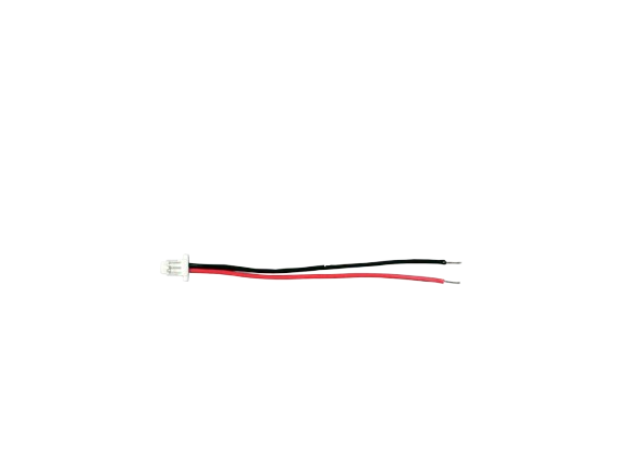
 Design with jst connector 2 pin in Cirkit Designer
Introduction
The JST Connector 2 Pin, manufactured by Battery (Part ID: JST), is a compact and reliable connector widely used in electronic circuits. It is designed to provide a secure and stable connection between wires, making it ideal for low-power applications. This connector is commonly found in battery packs, RC vehicles, LED strips, and other small electronic devices.
Explore Projects Built with jst connector 2 pin
 Open Project in Cirkit Designer
 Open Project in Cirkit Designer
 Open Project in Cirkit Designer
 Open Project in Cirkit Designer
Explore Projects Built with jst connector 2 pin
Open Project in Cirkit DesignerOpen Project in Cirkit DesignerOpen Project in Cirkit DesignerOpen Project in Cirkit DesignerCommon Applications and Use Cases
- Connecting battery packs to circuit boards
- Powering LED strips and small motors
- RC vehicles and drones
- Prototyping and DIY electronics projects
Technical Specifications
The following table outlines the key technical details of the JST Connector 2 Pin:
| Parameter | Specification |
|---|---|
| Manufacturer | Battery |
| Part ID | JST |
| Number of Pins | 2 |
| Connector Type | Wire-to-wire |
| Current Rating | Up to 3A |
| Voltage Rating | Up to 250V |
| Wire Gauge Support | 22-28 AWG |
| Operating Temperature | -25°C to 85°C |
| Material | Housing: Nylon, Contacts: Phosphor Bronze |
Pin Configuration and Descriptions
The JST Connector 2 Pin has two terminals, typically used for power and ground connections. The pin configuration is as follows:
| Pin Number | Description | Typical Use |
|---|---|---|
| 1 | Positive (+) Terminal | Power supply (VCC) |
| 2 | Negative (-) Terminal | Ground (GND) |
Usage Instructions
How to Use the JST Connector 2 Pin in a Circuit
- Prepare the Wires: Strip the insulation from the ends of the wires you want to connect, ensuring the exposed length matches the connector's crimp terminals.
- Crimp the Terminals: Use a crimping tool to attach the connector terminals to the stripped wire ends. Ensure a secure and firm crimp for reliable conductivity.
- Insert Terminals into the Housing: Push the crimped terminals into the JST connector housing until they click into place.
- Connect to the Circuit: Plug the JST connector into its corresponding counterpart or socket on the circuit board.
Important Considerations and Best Practices
- Wire Gauge: Ensure the wire gauge matches the connector's specifications (22-28 AWG) for optimal performance.
- Polarity: Double-check the polarity of the connections to avoid damage to the circuit or components.
- Secure Connection: Verify that the terminals are fully inserted into the housing to prevent loose connections.
- Avoid Overcurrent: Do not exceed the current rating (3A) to prevent overheating or damage.
Example: Connecting a JST Connector to an Arduino UNO
The JST Connector 2 Pin can be used to power an Arduino UNO from a battery pack. Below is an example of how to connect and use it:
- Connect the positive terminal of the JST connector to the VIN pin on the Arduino UNO.
- Connect the negative terminal of the JST connector to the GND pin on the Arduino UNO.
Sample Code for Testing the Connection
// This code blinks an LED connected to pin 13 of the Arduino UNO.
// Ensure the Arduino is powered via the JST connector.

void setup() {
  pinMode(13, OUTPUT); // Set pin 13 as an output
}

void loop() {
  digitalWrite(13, HIGH); // Turn the LED on
  delay(1000);            // Wait for 1 second
  digitalWrite(13, LOW);  // Turn the LED off
  delay(1000);            // Wait for 1 second
}
Troubleshooting and FAQs
Common Issues and Solutions
Loose Connection:
- Issue: The connector feels loose or disconnects easily.
- Solution: Ensure the terminals are fully inserted into the housing and the crimping is secure.
Polarity Reversal:
- Issue: The circuit does not work or components are damaged.
- Solution: Double-check the polarity of the connections before powering the circuit.
Overheating:
- Issue: The connector becomes hot during operation.
- Solution: Verify that the current does not exceed the 3A rating. Use thicker wires if necessary.
Wire Slipping Out:
- Issue: The wire detaches from the terminal.
- Solution: Use a proper crimping tool and ensure the wire is securely crimped.
FAQs
Q: Can the JST Connector 2 Pin handle high-power applications?
A: No, the connector is designed for low-power applications with a maximum current rating of 3A.
Q: Is the JST Connector 2 Pin waterproof?
A: No, this connector is not waterproof. For outdoor or waterproof applications, consider using a sealed connector.
Q: Can I reuse the connector housing and terminals?
A: The housing can be reused if undamaged, but the terminals are typically single-use due to deformation during crimping.
Q: What tools are required for crimping?
A: A dedicated JST crimping tool is recommended for precise and reliable crimps.