Cirkit Designer Logo
Cirkit Designer
Your all-in-one circuit design IDE
Home / 
Component Documentation

How to Use ESP32-36PINS-DEVKIT-V1: Examples, Pinouts, and Specs

Image of ESP32-36PINS-DEVKIT-V1
Cirkit Designer LogoDesign with ESP32-36PINS-DEVKIT-V1 in Cirkit Designer

Introduction

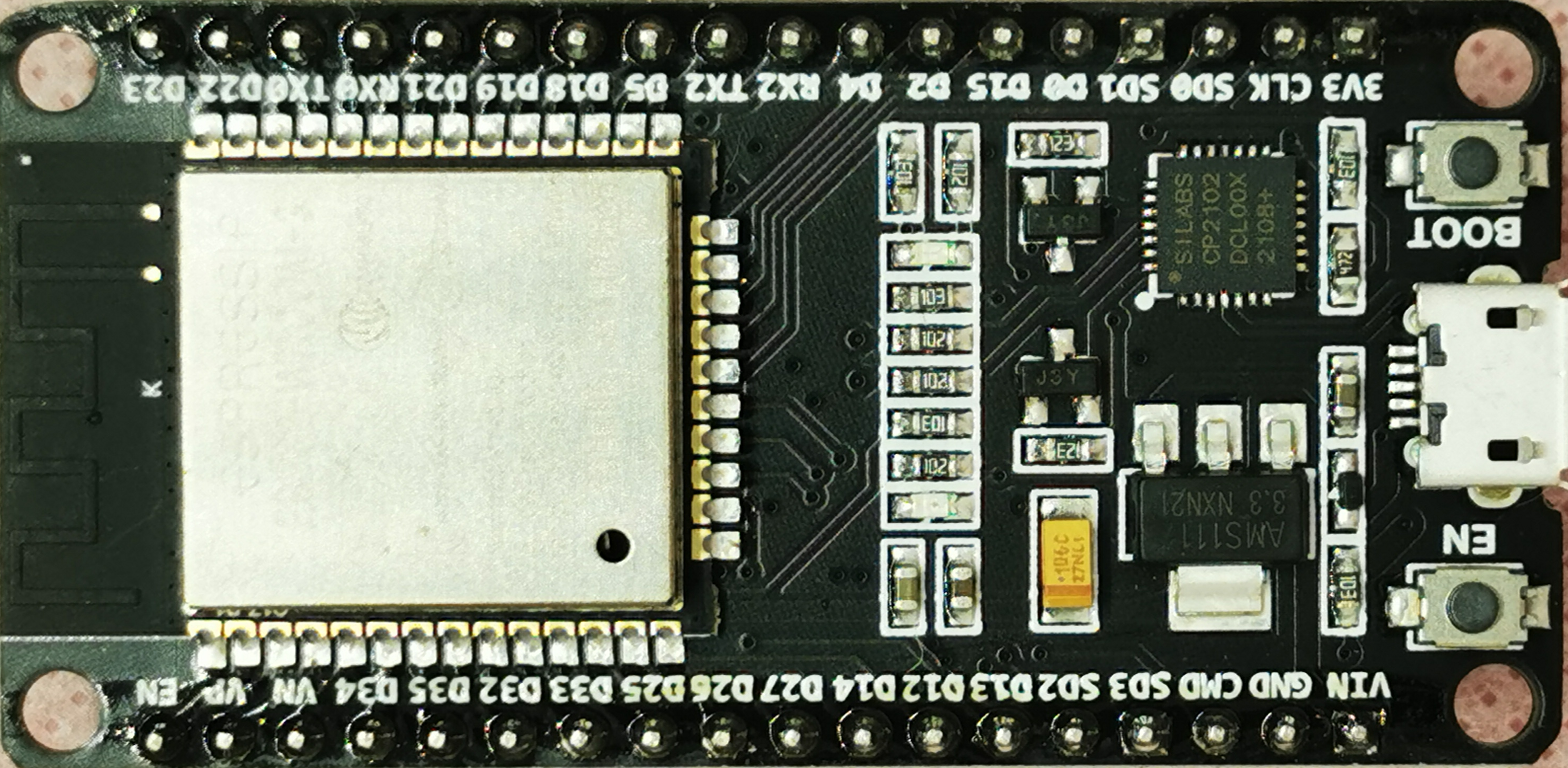
The ESP32-36PINS-DEVKIT-V1 is a versatile development kit based on the ESP32 module, designed by Espressif Systems. This kit is equipped with 36 GPIO pins and is widely used for Internet of Things (IoT) projects, wireless communication, and complex applications requiring multiple sensor integrations. It is an ideal choice for prototyping and developing applications such as smart home devices, wearable electronics, and industrial automation systems.

Explore Projects Built with ESP32-36PINS-DEVKIT-V1

Use Cirkit Designer to design, explore, and prototype these projects online. Some projects support real-time simulation. Click "Open Project" to start designing instantly!
ESP32 and Logic Level Converter-Based Wi-Fi Controlled Interface
Image of Toshiba AC ESP32 devkit v1: A project utilizing ESP32-36PINS-DEVKIT-V1 in a practical application
This circuit features an ESP32 Devkit V1 microcontroller connected to a Bi-Directional Logic Level Converter, which facilitates voltage level shifting between the ESP32 and external components. The ESP32 is powered through its VIN pin via an alligator clip cable, and the logic level converter is connected to various pins on the ESP32 to manage different voltage levels for communication.
Cirkit Designer LogoOpen Project in Cirkit Designer
ESP32-Based Environmental Monitoring System with Water Flow Sensing
Image of Water: A project utilizing ESP32-36PINS-DEVKIT-V1 in a practical application
This circuit features an ESP32 Devkit V1 microcontroller connected to a DHT22 temperature and humidity sensor and a water flow sensor. The ESP32 reads environmental data from the DHT22 via a digital input pin (D33) and monitors water flow through the water flow sensor connected to another digital input pin (D23). The ESP32 is powered through its VIN pin, and both sensors are powered by the ESP32's 3V3 output, with common ground connections.
Cirkit Designer LogoOpen Project in Cirkit Designer
ESP32-Based Environmental Monitoring and Alert System with Solar Charging
Image of mark: A project utilizing ESP32-36PINS-DEVKIT-V1 in a practical application
This circuit features an ESP32 Devkit V1 microcontroller connected to various sensors and modules for monitoring and communication purposes. It includes an MQ-2 gas sensor and a DHT11 temperature and humidity sensor, both interfaced with the ESP32 for environmental data collection. The circuit is powered by a 12V battery, regulated to 5V by step-down converters, and includes a solar charge controller connected to a solar panel for battery charging, a UPS module for power management, and a SIM900A module for GSM communication. Additionally, there is a WS2812 RGB LED strip for visual feedback and a piezo buzzer for audio alerts, both controlled by the ESP32.
Cirkit Designer LogoOpen Project in Cirkit Designer
ESP32 Devkit V1 and OLED Display Bitmap Viewer
Image of Esp32_monochromeimage: A project utilizing ESP32-36PINS-DEVKIT-V1 in a practical application
This circuit consists of an ESP32 Devkit V1 microcontroller connected to a 1.3" OLED display via I2C communication. The ESP32 initializes the OLED display and renders a predefined bitmap image on it.
Cirkit Designer LogoOpen Project in Cirkit Designer

Explore Projects Built with ESP32-36PINS-DEVKIT-V1

Use Cirkit Designer to design, explore, and prototype these projects online. Some projects support real-time simulation. Click "Open Project" to start designing instantly!
Image of Toshiba AC ESP32 devkit v1: A project utilizing ESP32-36PINS-DEVKIT-V1 in a practical application
ESP32 and Logic Level Converter-Based Wi-Fi Controlled Interface
This circuit features an ESP32 Devkit V1 microcontroller connected to a Bi-Directional Logic Level Converter, which facilitates voltage level shifting between the ESP32 and external components. The ESP32 is powered through its VIN pin via an alligator clip cable, and the logic level converter is connected to various pins on the ESP32 to manage different voltage levels for communication.
Cirkit Designer LogoOpen Project in Cirkit Designer
Image of Water: A project utilizing ESP32-36PINS-DEVKIT-V1 in a practical application
ESP32-Based Environmental Monitoring System with Water Flow Sensing
This circuit features an ESP32 Devkit V1 microcontroller connected to a DHT22 temperature and humidity sensor and a water flow sensor. The ESP32 reads environmental data from the DHT22 via a digital input pin (D33) and monitors water flow through the water flow sensor connected to another digital input pin (D23). The ESP32 is powered through its VIN pin, and both sensors are powered by the ESP32's 3V3 output, with common ground connections.
Cirkit Designer LogoOpen Project in Cirkit Designer
Image of mark: A project utilizing ESP32-36PINS-DEVKIT-V1 in a practical application
ESP32-Based Environmental Monitoring and Alert System with Solar Charging
This circuit features an ESP32 Devkit V1 microcontroller connected to various sensors and modules for monitoring and communication purposes. It includes an MQ-2 gas sensor and a DHT11 temperature and humidity sensor, both interfaced with the ESP32 for environmental data collection. The circuit is powered by a 12V battery, regulated to 5V by step-down converters, and includes a solar charge controller connected to a solar panel for battery charging, a UPS module for power management, and a SIM900A module for GSM communication. Additionally, there is a WS2812 RGB LED strip for visual feedback and a piezo buzzer for audio alerts, both controlled by the ESP32.
Cirkit Designer LogoOpen Project in Cirkit Designer
Image of Esp32_monochromeimage: A project utilizing ESP32-36PINS-DEVKIT-V1 in a practical application
ESP32 Devkit V1 and OLED Display Bitmap Viewer
This circuit consists of an ESP32 Devkit V1 microcontroller connected to a 1.3" OLED display via I2C communication. The ESP32 initializes the OLED display and renders a predefined bitmap image on it.
Cirkit Designer LogoOpen Project in Cirkit Designer

Technical Specifications

Key Technical Details

  • Microcontroller: Tensilica LX6 dual-core processor
  • Operating Voltage: 3.3V
  • Input Voltage: 7-12V (via Vin pin), 5V (via micro USB)
  • Digital I/O Pins: 36 (multiplexed with other functions)
  • Analog Input Pins: 18 (multiplexed with digital pins)
  • Flash Memory: 4MB
  • SRAM: 520 KB
  • Clock Speed: Up to 240MHz
  • Wi-Fi: 802.11 b/g/n
  • Bluetooth: v4.2 BR/EDR and BLE
  • Operating Temperature: -40°C to +125°C

Pin Configuration and Descriptions

Pin Number Function Description
1-36 GPIO0 - GPIO35 General Purpose Input/Output pins, various functions

Note: The above table is a simplified representation. Each GPIO pin has multiple functions, and the exact pinout should be referred to from the ESP32 datasheet or pinout diagram provided by Espressif.

Usage Instructions

Integrating with a Circuit

  1. Powering the ESP32-DEVKIT-V1: Connect a 5V power supply to the micro USB port or supply 7-12V to the Vin pin.
  2. Connecting to a Computer: Use a micro USB cable to connect the board to a computer for programming.
  3. GPIO Pin Usage: Refer to the pinout diagram to understand the multiplexed functions of each GPIO pin.
  4. Programming: Use the Arduino IDE or other supported IDEs to program the ESP32. Ensure you have the necessary board packages installed.

Best Practices

  • Always use a voltage regulator when supplying power through the Vin pin to prevent damage.
  • Avoid drawing more than 12mA from any GPIO pin.
  • Use external pull-up or pull-down resistors with GPIO pins when required.
  • Ensure that the antenna area is clear of metal components to avoid signal interference.

Example Code for Arduino UNO

// Simple Blink example for ESP32-36PINS-DEVKIT-V1

#define LED_BUILTIN 2 // Define the LED_BUILTIN pin. It's usually GPIO 2

void setup() {
  pinMode(LED_BUILTIN, OUTPUT); // Initialize the LED_BUILTIN pin as an output
}

void loop() {
  digitalWrite(LED_BUILTIN, HIGH); // Turn the LED on
  delay(1000);                     // Wait for a second
  digitalWrite(LED_BUILTIN, LOW);  // Turn the LED off
  delay(1000);                     // Wait for a second
}

Note: The above code is a simple blink example. The LED_BUILTIN constant may vary depending on the board revision.

Troubleshooting and FAQs

Common Issues

  • Board not detected: Ensure the micro USB cable is properly connected and the computer's USB port is functioning.
  • Failed to connect to Wi-Fi: Check the Wi-Fi credentials and signal strength. Ensure the antenna area is not obstructed.
  • Unexpected resets: This can be caused by insufficient power supply or a faulty connection. Check the power source and wiring.

Solutions and Tips

  • Use quality USB cables and power supplies.
  • When encountering programming issues, hold the BOOT button when starting the upload process.
  • For deep sleep issues, ensure that the correct wake-up conditions are set in the code.

FAQs

Q: Can I use the ESP32-DEVKIT-V1 with the Arduino IDE? A: Yes, you can program the ESP32-DEVKIT-V1 using the Arduino IDE by installing the ESP32 board package.

Q: What is the maximum current that can be drawn from a GPIO pin? A: It is recommended not to draw more than 12mA from a GPIO pin to prevent damage to the board.

Q: How do I enable Bluetooth functionality? A: Bluetooth can be enabled through programming using the appropriate libraries and functions provided by the ESP-IDF or the Arduino ESP32 board package.

For more detailed information, refer to the official documentation and resources provided by Espressif Systems.