Cirkit Designer Logo
Cirkit Designer
Your all-in-one circuit design IDE
Home / 
Component Documentation

How to Use STWD100: Examples, Pinouts, and Specs

Image of STWD100
Cirkit Designer LogoDesign with STWD100 in Cirkit Designer

Introduction

The STWD100 is a low-power supervisor and watchdog integrated circuit (IC) designed to monitor system operation and provide a reset signal to the host microcontroller or processor. It ensures that systems operate reliably by resetting the system if the power supply drops below a predefined threshold or if the watchdog timer is not serviced within a specified time period. This component is commonly used in microcontroller-based systems, such as embedded systems, consumer electronics, and automotive applications, to enhance system stability and reliability.

Explore Projects Built with STWD100
Use Cirkit Designer to design, explore, and prototype these projects online. Some projects support real-time simulation. Click "Open Project" to start designing instantly!
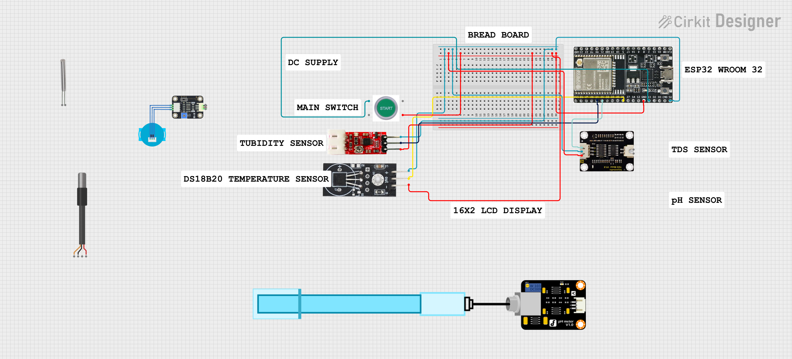
ESP32-Based Water Quality Monitoring System with DS18B20 and Turbidity Sensor
Image of Copy of AquaSense: A project utilizing STWD100 in a practical application
This circuit is a water quality monitoring system that uses an ESP32 microcontroller to measure TDS, pH, temperature, and turbidity of water. The system includes sensors for each parameter and a start switch, with data being displayed on a 16x2 I2C LCD and logged via serial communication.
Cirkit Designer LogoOpen Project in Cirkit Designer
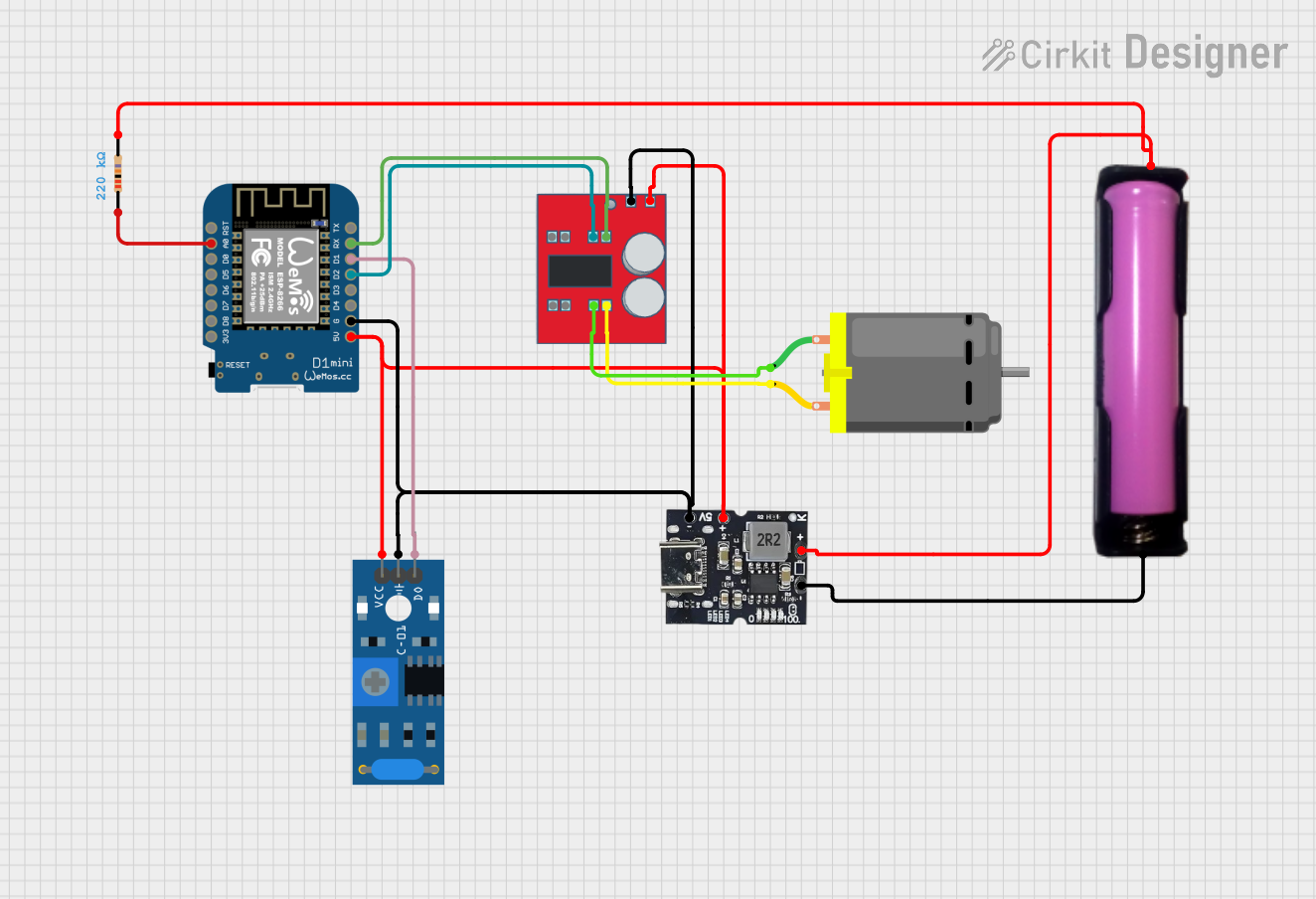
Wi-Fi Controlled Vibration-Sensing Robot with Battery Monitoring
Image of Vibration Trash: A project utilizing STWD100 in a practical application
This circuit features a Wemos D1 Mini microcontroller connected to a MX1508 DC Motor Driver for controlling a DC motor, a SW-420 Vibration Sensor for detecting vibrations, and a Type-c Power Bank Module with an 18650 battery holder for power supply. The microcontroller monitors the vibration sensor and controls the motor driver based on the sensor's output, while also measuring the battery voltage through an ADC pin with a connected resistor for voltage scaling. The embedded code enables WiFi connectivity, OTA updates, and integration with Home Assistant for remote monitoring and control.
Cirkit Designer LogoOpen Project in Cirkit Designer
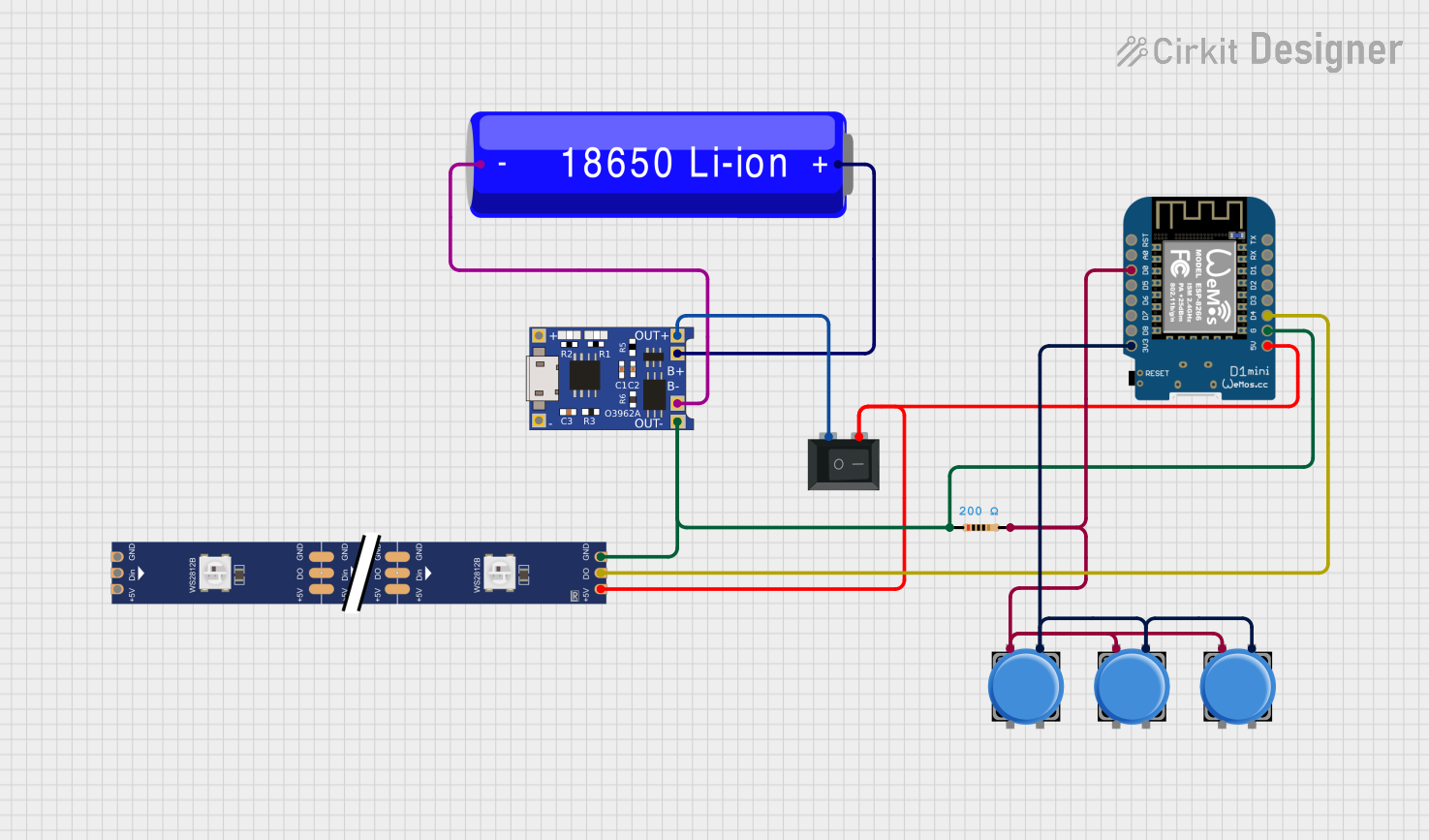
Wi-Fi Controlled RGB LED Strip with Battery Management System
Image of OpenTimingProject - Basic node: A project utilizing STWD100 in a practical application
This circuit features a Wemos D1 Mini microcontroller powered by a 18650 Li-ion battery through a TP4056 charging module, with power control managed by a rocker switch. The Wemos D1 Mini controls a WS2812 RGB LED strip, with the data line connected to the D4 pin and power lines controlled by the switch. Multiple pushbuttons are connected to the D0 pin through a resistor, likely for user input to control the LED strip or other functions in the microcontroller's code.
Cirkit Designer LogoOpen Project in Cirkit Designer
I2C-Controlled OLED Display with External EEPROM and Interactive Pushbuttons
Image of godmode: A project utilizing STWD100 in a practical application
This is a microcontroller-based interactive device featuring a Wemos D1 Mini, an OLED display, external EEPROM, and an I/O expander. It includes user input buttons and status LEDs, with potential MIDI interface capabilities.
Cirkit Designer LogoOpen Project in Cirkit Designer

Explore Projects Built with STWD100

Use Cirkit Designer to design, explore, and prototype these projects online. Some projects support real-time simulation. Click "Open Project" to start designing instantly!
Image of Copy of AquaSense: A project utilizing STWD100 in a practical application
ESP32-Based Water Quality Monitoring System with DS18B20 and Turbidity Sensor
This circuit is a water quality monitoring system that uses an ESP32 microcontroller to measure TDS, pH, temperature, and turbidity of water. The system includes sensors for each parameter and a start switch, with data being displayed on a 16x2 I2C LCD and logged via serial communication.
Cirkit Designer LogoOpen Project in Cirkit Designer
Image of Vibration Trash: A project utilizing STWD100 in a practical application
Wi-Fi Controlled Vibration-Sensing Robot with Battery Monitoring
This circuit features a Wemos D1 Mini microcontroller connected to a MX1508 DC Motor Driver for controlling a DC motor, a SW-420 Vibration Sensor for detecting vibrations, and a Type-c Power Bank Module with an 18650 battery holder for power supply. The microcontroller monitors the vibration sensor and controls the motor driver based on the sensor's output, while also measuring the battery voltage through an ADC pin with a connected resistor for voltage scaling. The embedded code enables WiFi connectivity, OTA updates, and integration with Home Assistant for remote monitoring and control.
Cirkit Designer LogoOpen Project in Cirkit Designer
Image of OpenTimingProject - Basic node: A project utilizing STWD100 in a practical application
Wi-Fi Controlled RGB LED Strip with Battery Management System
This circuit features a Wemos D1 Mini microcontroller powered by a 18650 Li-ion battery through a TP4056 charging module, with power control managed by a rocker switch. The Wemos D1 Mini controls a WS2812 RGB LED strip, with the data line connected to the D4 pin and power lines controlled by the switch. Multiple pushbuttons are connected to the D0 pin through a resistor, likely for user input to control the LED strip or other functions in the microcontroller's code.
Cirkit Designer LogoOpen Project in Cirkit Designer
Image of godmode: A project utilizing STWD100 in a practical application
I2C-Controlled OLED Display with External EEPROM and Interactive Pushbuttons
This is a microcontroller-based interactive device featuring a Wemos D1 Mini, an OLED display, external EEPROM, and an I/O expander. It includes user input buttons and status LEDs, with potential MIDI interface capabilities.
Cirkit Designer LogoOpen Project in Cirkit Designer

Technical Specifications

Key Features

  • Operating voltage range: 2.5V to 5.5V
  • Low current consumption: 13 µA typ.
  • Watchdog timer with 3.4 ms to 33.6 seconds timeout range
  • Open-drain or push-pull reset output options
  • Temperature range: -40°C to +125°C

Pin Configuration and Descriptions

Pin Number Name Description
1 WDI Watchdog input. A transition on this pin resets the watchdog timer.
2 GND Ground. Connect to the system ground plane.
3 VCC Power supply input. Connect to a 2.5V to 5.5V source.
4 RESET Reset output. Active low signal that indicates a reset condition.

Usage Instructions

Integration into a Circuit

  1. Connect the VCC pin to a stable power supply within the 2.5V to 5.5V range.
  2. Ground the GND pin to the system's ground plane.
  3. Connect the RESET pin to the reset input of the microcontroller or processor.
  4. Service the WDI pin by toggling it within the watchdog timer period to prevent a system reset.

Best Practices

  • Use a decoupling capacitor (typically 0.1 µF) close to the VCC pin to filter out noise.
  • Ensure that the WDI pin is serviced within the specified timeout period to prevent unnecessary resets.
  • Choose the appropriate RESET output type (open-drain or push-pull) based on the system requirements.
  • Avoid placing noisy components near the STWD100 to prevent false triggering.

Example Code for Arduino UNO

// Example code to service the STWD100 watchdog timer using an Arduino UNO

const int watchdogInputPin = 2; // Connect WDI pin of STWD100 to digital pin 2

void setup() {
  pinMode(watchdogInputPin, OUTPUT);
  // Start with a high signal
  digitalWrite(watchdogInputPin, HIGH);
}

void loop() {
  // Toggle the WDI pin to reset the watchdog timer
  digitalWrite(watchdogInputPin, LOW);
  delay(1); // Wait for 1ms
  digitalWrite(watchdogInputPin, HIGH);
  
  // Your main code would go here
  
  // Make sure to toggle the WDI pin within the watchdog's timeout period
  delay(1000); // Example delay to simulate work (adjust as needed)
}

Troubleshooting and FAQs

Common Issues

  • System Resets Unexpectedly: Ensure that the WDI pin is being toggled within the watchdog's timeout period. Also, check the power supply for stability.
  • No Reset Signal on Power Drop: Verify that the VCC is connected properly and that the voltage is within the specified range.

FAQs

Q: Can the STWD100 be used with voltages lower than 2.5V? A: No, the STWD100 is designed to operate within a 2.5V to 5.5V range. Using it outside this range may result in unreliable performance or damage to the IC.

Q: How do I choose between the open-drain and push-pull RESET output? A: The choice depends on your system's requirements. Open-drain outputs require an external pull-up resistor and allow for wired-OR connections, while push-pull outputs can directly drive the load.

Q: What is the typical current consumption of the STWD100? A: The typical current consumption is 13 µA, making it suitable for low-power applications.

For further assistance or technical support, please contact the manufacturer or refer to the STWD100 datasheet.